Telecom relays and signal relays are fundamental components in modern communication infrastructure, enabling reliable switching, amplification, and routing of electronic signals across telephone networks, broadband systems, satellite links, and industrial automation platforms. Compact in form yet critical in function, these devices ensure stable signal paths under varying electrical loads and environmental conditions. This article covers their core types, technical specifications, real-world applications, and selection criteria to help engineers and procurement professionals make informed decisions.
What Are Telecom Relays and Signal Relays?
Telecom relays are electromechanical or solid-state switching devices designed specifically for telecommunications systems. They operate at low signal levels — typically switching currents of 10 mA to 2 A and voltages of 5 V to 48 V DC — while providing high isolation between the control circuit and the switched circuit. Signal relays are a closely related category, optimized for routing low-level analog or digital signals with minimal insertion loss and crosstalk.
Both relay types share a common goal: maintaining signal integrity across millions of switching cycles without degradation. According to IEC 61810 (the international standard governing electromechanical elementary relays), key performance parameters include contact resistance, dielectric strength, and mechanical endurance — parameters that directly affect network reliability.
Core Distinctions Between Telecom and Signal Relays
Table 1: Key parameter comparison between telecom relays and signal relays in typical applications
| Parameter |
Telecom Relay |
Signal Relay |
| Switching Current Range |
10 mA – 2 A |
1 mA – 500 mA |
| Coil Voltage (typical) |
5 V, 12 V, 24 V, 48 V DC |
3 V, 5 V, 12 V DC |
| Contact Resistance |
≤ 100 mΩ |
≤ 50 mΩ |
| Mechanical Endurance |
Up to 108 operations |
Up to 109 operations |
| Primary Use |
PSTN, PBX, DSL, fiber networks |
Test equipment, audio, data routing |
Main Types of Telecom Relays and Their Technical Features
Understanding the relay types available helps engineers match device characteristics to system demands. The three dominant categories in telecom and signal relay applications each offer distinct tradeoffs between switching speed, isolation voltage, and power consumption.
Electromechanical Relays (EMR)
Electromechanical relays use a coil to generate a magnetic field that physically moves a contact armature. They are widely used in PSTN switching, PBX systems, and industrial control due to their galvanic isolation and ability to handle both AC and DC loads. A typical telecom EMR offers coil sensitivity of 100–200 mW and contact ratings up to 2 A at 30 V DC. Their mechanical nature means they produce an audible click, which is sometimes used as a diagnostic indicator in maintenance.
Reed Relays
Reed relays enclose two ferromagnetic contacts inside a sealed glass tube filled with inert gas. When current passes through the surrounding coil, the contacts snap together. Because they are hermetically sealed, reed relays achieve contact resistance as low as 30 mΩ and can complete switching cycles in under 1 ms. They are commonly used in automated test equipment (ATE), medical instrumentation, and low-level signal routing where contamination of contacts must be prevented. Electrical endurance exceeds 108 operations at rated signal loads.
Solid-State Relays (SSR)
Solid-state relays use semiconductor components — typically MOSFETs or thyristors — to perform switching without any moving parts. This results in silent operation, switching speeds below 1 ms, and lifetimes theoretically unlimited by mechanical wear. However, SSRs introduce a small on-state voltage drop (typically 1–1.5 V), generate heat under load, and provide lower isolation voltages compared to EMRs. They are preferred in high-cycle applications such as telecom exchange cards and data center switching fabrics.
Key Applications of Telecom Relays Across Industries
Telecom relays serve as signal gatekeepers across a broad range of industries. Their ability to switch low-level signals reliably makes them indispensable wherever communication paths must be established, maintained, or rerouted under software control.
- Public Switched Telephone Networks (PSTN): Line cards in central office equipment use telecom relays to connect subscriber lines, route calls, and perform loop testing. A single central office may contain hundreds of thousands of relay contacts.
- DSL and Broadband Infrastructure: DSLAM (Digital Subscriber Line Access Multiplexer) line cards incorporate signal relays to switch between voice and data paths, enabling ADSL2+ and VDSL2 services with downstream rates up to 100 Mbps.
- Private Branch Exchange (PBX) Systems: Corporate PBX platforms rely on miniature signal relays to switch internal extensions and interface with external telephone trunks, handling coil voltages of 12 V or 24 V DC.
- Satellite Communication Ground Stations: RF signal relays route microwave signals between antenna feeds and processing equipment, with specialized models operating up to 3 GHz.
- Industrial Automation and Smart Grid: Protective relays in power distribution systems use signal relay outputs to trigger alarms, isolate faults, and communicate status data to SCADA systems.
- Automotive Electronics: Modern vehicles use miniature signal relays in telematics control units (TCUs), infotainment systems, and advanced driver assistance systems (ADAS) to manage communication bus switching.
Estimated Share of Telecom Relay Demand by Application Sector (2024)
PSTN & Telecom Infrastructure
28%
Industrial Automation
22%
Automotive Electronics
19%
Satellite & RF Systems
11%
Source: Estimated based on industry segment analysis, relay procurement patterns, and published market research (2024). PSTN and telecom infrastructure continue to represent the largest single demand segment, driven by ongoing network maintenance and expansion in developing markets. Industrial automation and automotive electronics are the fastest-growing application sectors, reflecting the integration of communication relays into smart manufacturing and connected vehicle platforms. The diversification of demand across segments underscores the cross-industry relevance of reliable signal relay technology.
Critical Technical Parameters When Selecting Telecom and Signal Relays
Choosing the right relay for a telecom or signal application requires careful evaluation of electrical, mechanical, and environmental specifications. Overlooking any of these parameters can lead to premature contact failure, signal degradation, or system downtime.
Coil Sensitivity and Power Consumption
Coil sensitivity is expressed as the minimum coil power (in milliwatts) required to reliably energize the relay. Telecom relays commonly have coil sensitivities between 100 mW and 360 mW. In battery-backed or energy-constrained systems such as remote telecom equipment, lower coil power directly extends backup runtime. Some modern low-power signal relays achieve coil sensitivities below 50 mW while maintaining 500 V AC dielectric strength between coil and contacts.
Contact Form and Pole Configuration
Standard contact forms for telecom relays include:
- SPST-NO (Form A): Single pole, normally open — used where a circuit must close on energization.
- SPDT (Form C): Single pole, double throw — the most common configuration in line-switching applications, routing a signal to one of two paths.
- DPDT (2 Form C): Dual pole, double throw — used where two independent circuits must switch simultaneously, common in PBX line cards.
- Latching (Bistable): Maintains position without continuous coil power, used in energy-saving applications where the relay state rarely changes.
Dielectric Strength and Isolation
For safety-critical telecom applications, dielectric strength between open contacts is typically rated at 500 V AC to 1,000 V AC (1 minute, per IEC 61810). Coil-to-contact isolation is often rated at 1,500 V AC or higher. High isolation is especially important in systems that interface with PSTN lines, where transient surges from lightning or line faults can reach several kilovolts.
Operating Temperature Range
Standard telecom relays are rated for -40°C to +85°C operating temperature, with some industrial-grade models specified to -55°C. Temperature affects both the coil resistance (which increases with heat, requiring derating of operate voltage) and contact material performance. Gold-clad silver contacts, used in signal relays, maintain low and stable resistance across this range even at sub-milliamp switching levels where base metal contacts would form insulating oxides.
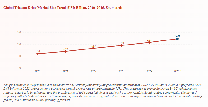
Development Trends Shaping the Telecom Relay Market
The telecom relay market is being reshaped by the convergence of 5G infrastructure deployment, fiber optic expansion, smart grid modernization, and the miniaturization demands of IoT devices. These trends are driving demand for relays with lower power budgets, smaller footprints, and enhanced environmental sealing.
Miniaturization and SMD Packaging
As PCB designs become denser, relay manufacturers have developed surface-mount device (SMD) packages with footprints as small as 5 mm × 3.5 mm. These miniature signal relays maintain the same electrical performance as through-hole predecessors while enabling automated reflow soldering and high-density placement. The HELISHUN product range includes SMD telecom relays designed to IPC-7711/7721 rework standards.
Low-Power Design for 5G and IoT Nodes
5G base station remote radio units (RRUs) and IoT gateway devices operate on strict power budgets. Next-generation telecom signal relays for these platforms are being developed with coil power consumption below 100 mW at 3.3 V or 5 V supply rails, enabling direct GPIO-level drive from microcontrollers without buffer transistors. This simplifies board design and reduces component count.
Fiber Optic and High-Speed Data Network Integration
While fiber optic systems use optical switching for data transmission, their management and protection planes still rely heavily on electromechanical telecom relays for path switching, alarm routing, and protection switching. ROADM (Reconfigurable Optical Add-Drop Multiplexer) systems, which form the backbone of modern WDM optical networks, use arrays of signal relays to configure optical paths without converting signals back to the electrical domain.
Smart Grid and Industrial IoT Applications
Smart grid deployments are creating substantial demand for telecom-grade signal relays in remote terminal units (RTUs) and intelligent electronic devices (IEDs). These relays must satisfy IEC 61850 communication protocol requirements and withstand high-energy transients per IEC 61000-4-5. In 2023, global smart grid investment exceeded USD 70 billion, with relay-intensive protection and automation equipment representing a significant portion of this spending.
Compliance Standards and Certifications for Telecom Relays
International compliance certifications are not optional in professional telecom procurement — they are baseline requirements that validate safety, performance, and environmental compliance. The following standards are most relevant to telecom relay selection:
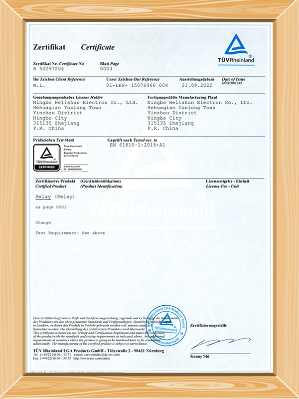
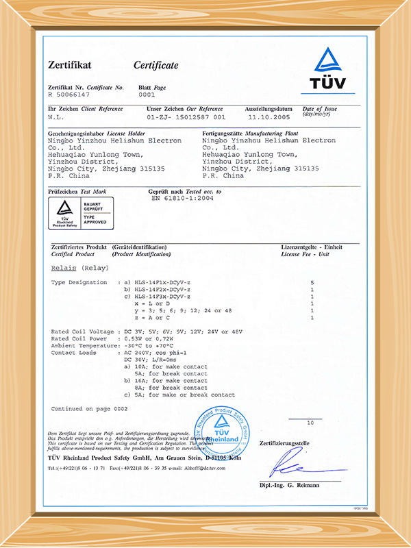
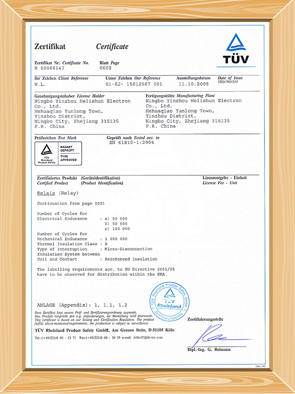
- IEC 61810: The primary international standard for electromechanical elementary relays, covering test methods, performance requirements, and marking.
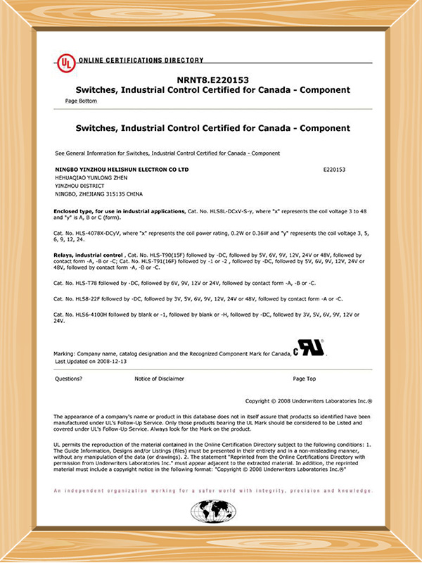
- UL 508 / UL 873: North American safety standards for industrial control equipment and temperature-indicating control relays, administered by Underwriters Laboratories.
- CE Marking (EU): Confirms conformity with EU directives including the Low Voltage Directive (LVD 2014/35/EU) and the EMC Directive (2014/30/EU).
- RoHS Directive (2011/65/EU): Restricts the use of hazardous substances including lead, mercury, cadmium, and certain brominated flame retardants in electronic components.
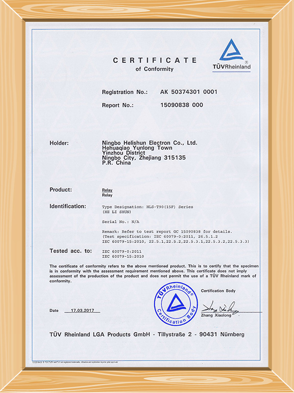
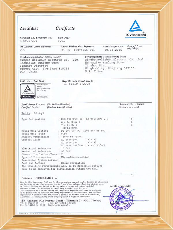
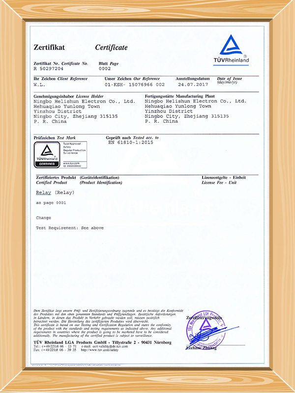
- TUV Rheinland: German testing and certification for functional safety and product performance, widely recognized in European and global markets.
- CQC (China Quality Certification): Mandatory for products sold in the Chinese domestic market under the China Compulsory Certification (CCC) framework.
- ISO 9001:2015: Quality management system certification ensuring consistent manufacturing processes and continuous improvement across the production lifecycle.
Procuring relays from a manufacturer that holds all relevant certifications — UL, TUV, CE, RoHS, CQC, and ISO 9001:2015 — significantly reduces qualification lead times and simplifies regulatory documentation for end-product certification.
How to Evaluate Telecom Relay Reliability and Longevity
Relay reliability in telecom applications is determined by a combination of contact material selection, sealing strategy, and operating load relative to the rated maximum. Engineers can use the following framework to evaluate long-term performance:
- Contact load ratio: Operating a relay at 10–30% of its rated contact load (the "signal load" range) maximizes electrical endurance. Running contacts near rated capacity accelerates arc erosion and oxidation.
- Coil drive method: Using a peak-and-hold coil drive circuit reduces coil dissipation by up to 70% after initial energization, lowering thermal stress on coil insulation.
- Sealing grade: Flux-sealed (wash-tight) relays prevent contamination during wave soldering. Hermetically sealed relays (tested to MIL-STD-202) are required in high-humidity or high-altitude environments.
- Derating for temperature: At 85°C ambient, coil resistance increases by approximately 20% relative to 25°C, requiring operation voltage adjustment per manufacturer derating curves.
- Shock and vibration rating: Telecom relays in transport or outdoor enclosure applications should be evaluated against IEC 60068-2-6 (vibration) and IEC 60068-2-27 (shock) test standards.
About Ningbo Helishun Electron Co., Ltd.
Ningbo Helishun Electron Co., Ltd. was founded in 2000 and is located in Ningbo City, the major eastern seaport on the coastline of the East China Sea. The company now covers 8,800 square meters of manufacturing and research space, specializing in researching, developing, and producing relays, and holding a recognized position in the global relay market under the registered trademark HELISHUN.
Helishun has introduced advanced technology and testing equipment from domestic and international sources, and has built a dependable quality management system certified to ISO 9001:2015. Products carry internationally recognized certifications including UL, TUV, CE, CQC, and comply fully with EU RoHS requirements. The dimensional and mounting characteristics of HELISHUN relays are maintained consistent with equivalent international products, making them a suitable replacement option in existing designs.
HELISHUN relays are distributed across domestic and international markets and are widely used in household appliances, telecommunications, automation control, automotive electronics, instrumentation, and metering systems. The company pursues quality through all-around management and has earned broad customer trust through careful manufacturing and attentive service. OEM and ODM collaboration is welcomed, and customers are encouraged to visit the facility in Ningbo for in-depth technical discussions.
Frequently Asked Questions
Q1: What is the difference between a telecom relay and a power relay?
A1: Telecom relays are designed to switch low-level signals — typically under 2 A and 50 V DC — with very low contact resistance (under 100 mΩ) and high electrical endurance. Power relays are built to switch higher loads, often 10 A to 40 A or more, where contact erosion resistance is prioritized over low resistance. Using a power relay in a signal application often results in unreliable switching due to contact oxidation at sub-milliamp loads.
Q2: Can telecom relays be used in high-humidity environments?
A2: Standard telecom relays with flux-sealed or dust-cover enclosures perform adequately in controlled indoor environments up to 85% relative humidity (non-condensing). For outdoor telecom cabinets, marine installations, or tropical climates where condensation is possible, select relays with hermetically sealed or fully sealed epoxy enclosures tested per IEC 60068-2-78.
Q3: How do I drive a telecom relay directly from a microcontroller GPIO pin?
A3: Most GPIO pins supply 3.3 V or 5 V at 8–40 mA maximum. A relay requiring 150 mW at 5 V draws 30 mA, which may exceed GPIO current limits. A standard NPN transistor (such as 2N2222 or BC547) with a base resistor allows the GPIO to switch the transistor, which then drives the relay coil. Always include a flyback diode (such as 1N4007) across the coil to suppress the back-EMF spike when the relay de-energizes.
Q4: What certifications should I look for when sourcing telecom relays for EU markets?
A4: For EU market access, the relay should carry CE marking (confirming LVD and EMC directive compliance) and a RoHS declaration of conformity. TUV or equivalent third-party certification to IEC 61810 adds credibility during product qualification audits. If the end product also targets North America, concurrent UL recognition simplifies dual-market compliance.
Q5: What is a latching relay and when is it preferred over a standard telecom relay?
A5: A latching (bistable) relay uses two coil pulses — one to set and one to reset — and maintains its contact position without continuous power. This makes it suitable for applications where power consumption between switching events must be minimized, such as smart meters, remote terminal units, and battery-operated telecom nodes. The tradeoff is that the contact position is lost if power is cut before a reset pulse, so the system must initialize relay states on startup.
Q6: How long do telecom relays typically last?
A6: Mechanical endurance (coil cycles without electrical load) for modern telecom relays is commonly rated at 107 to 108 operations. Electrical endurance at rated signal load is typically 105 to 106 operations, depending on contact material and load conditions. Operating at 10–30% of rated load significantly extends contact life. In low-cycle telecom line card applications switching fewer than 100 times per day, well-made relays can deliver service lives exceeding 20 years.


 English
 中文简体
中文简体


 12-11-2021 Company News
 12-11-2021 Company News


