



 English
 中文简体
中文简体Content
- 1 The Basic Working Principle Of An Electromagnetic Relay
- 2 Isometric View Of A Relay Internal Structure
- 3 Electromagnetic Relays Compared With Solid State Relays
- 4 Reading A Relay Datasheet: Coil Voltage And Contact Rating
- 5 Response Time And Operating Life Considerations
- 6 Contact Configurations: Understanding NO, NC, And Changeover
- 7 Protecting The Coil Circuit: Why A Flyback Diode Matters
- 8 Classifying Relays By Mounting Style And Function
- 9 Environmental Ratings And Insulation Considerations
- 10 Where Relays Are Commonly Used
- 11 Certification And Quality Testing For Relay Products
- 12 About Ningbo Helishun Electron Co Ltd
- 13 A Practical Checklist For Selecting A Relay
- 14 Frequently Asked Questions
A relay works by using a small control signal to open or close a separate, often much larger, electrical circuit through an electromagnet and a set of mechanical contacts, which allows a low power control circuit to safely switch a high power load circuit without the two circuits touching directly. This basic principle is why relays remain central to household electrical appliances, automation control panels, automobile electronics, and telecommunication equipment today. The sections below walk through the internal structure of a relay, the difference between electromagnetic and solid state designs, how to read a relay datasheet, and where Ningbo Helishun Electron Co., Ltd fits into this picture as a relay manufacturer.
The Basic Working Principle Of An Electromagnetic Relay
An electromagnetic relay contains four core parts working together, an electromagnet coil, an armature, a spring, and a set of contacts. When a small control voltage is applied to the coil, current flowing through the coil winding generates a magnetic field around an iron core, and this field pulls the armature toward the core. The armature movement is what physically opens or closes the connected contacts, completing or breaking the separate load circuit that the relay is controlling.
When the control voltage is removed, the magnetic field collapses, and a return spring pulls the armature back to its resting position, restoring the contacts to their original state. This is the same operating logic described in general electromagnetism references such as the IEEE description of electromechanical switching devices, where a control winding converts electrical energy into a mechanical force strong enough to move a contact arm.
Isometric View Of A Relay Internal Structure
The diagram below illustrates the internal layout of a typical electromagnetic relay in an isometric style, showing how the coil, armature, and contact set are arranged inside the housing.
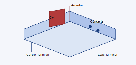
This isometric schematic shows the general internal arrangement common across many electromagnetic relay designs rather than one specific product drawing. The coil sits at the center of the structure since it is the component that generates the magnetic field once control voltage is applied. The armature is drawn extending upward from the coil area because its movement is the mechanical link between the electromagnet and the contact set. The contact points shown on the right side represent where the load circuit is physically opened or closed as the armature shifts position. The control terminal and load terminal are separated on opposite sides of the diagram to reflect how a relay keeps the low voltage control side electrically isolated from the higher power load side. Understanding this layout helps explain why relay coil voltage and contact rating are always listed as separate specifications on a datasheet.
Electromagnetic Relays Compared With Solid State Relays
Electromagnetic relays use a physical armature and contacts, which means switching involves a small mechanical movement each time the relay activates. Solid state relays instead use semiconductor components to switch the load circuit without any moving parts, which changes several practical characteristics buyers often compare.
| Characteristic | Electromagnetic Relay | Solid State Relay |
|---|---|---|
| Switching method | Mechanical contacts | Semiconductor junction |
| Audible operation | Slight click sound | Silent operation |
| Isolation approach | Physical air gap | Opto isolation |
| Common use case | General household and automation switching | Frequent cycling and precision control |
Reading A Relay Datasheet: Coil Voltage And Contact Rating
Two numbers matter most when selecting a relay for a specific application, the coil voltage and the contact rating. Coil voltage describes how much control voltage is needed to energize the electromagnet, common values include 5V, 12V, and 24V DC depending on the control circuit design. Contact rating describes the maximum voltage and current the load side contacts can safely switch, and this figure must always be matched to the actual load rather than assumed.
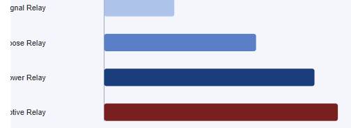
This bar chart offers an illustrative comparison of relative current handling across common relay categories rather than exact figures from a single datasheet. Signal relays sit at the lower end because they are designed for switching small control level signals rather than heavy loads. General purpose relays extend further, reflecting their role in household electrical appliance circuits and general automation panels. Power relays are shown with a longer bar since they are built specifically to handle sustained higher current loads in industrial and control cabinet settings. High current automotive relays extend furthest because vehicle electrical systems often need to switch substantial current to motors, pumps, and lighting circuits. Matching a relay category to the actual load current is a fundamental step in relay selection, and contact ratings should always be confirmed against the specific datasheet for the part being used.
Response Time And Operating Life Considerations
Response time refers to how quickly a relay contact changes state after the coil receives a control signal, and this figure matters most in applications where timing accuracy affects the overall system, such as automation control sequences.
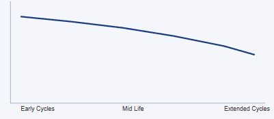
This line chart illustrates a general contact performance trend across the switching life of a relay rather than measured data from one specific test run. Performance stays relatively steady during early cycles because contact surfaces are still close to their original condition. A gradual decline appears through mid life cycles, which reflects the natural wear that occurs at contact points during repeated mechanical switching and arcing. The decline continues into extended cycle counts, illustrating why relay datasheets list a rated mechanical and electrical life rather than claiming unlimited switching capability. This pattern is consistent with general findings published in electromechanical component life testing literature, where contact wear accumulates gradually rather than failing abruptly under normal rated conditions. Selecting a relay rated for the expected switching frequency of an application helps ensure the component performs reliably across its intended service period.
Contact Configurations: Understanding NO, NC, And Changeover
Relay contacts are described by their resting state when no control voltage is applied. A normally open contact, commonly labeled NO, stays disconnected until the coil is energized, which is the configuration most often chosen when a circuit should remain off by default. A normally closed contact, labeled NC, stays connected until the coil is energized, which is used when a circuit needs to remain active until a control signal deliberately interrupts it, such as in certain safety interlock designs.
A changeover contact, sometimes written as SPDT for single pole double throw, combines both behaviors in one relay by switching a common terminal between an NO path and an NC path as the armature moves. Selecting the correct contact configuration is as important as selecting the correct coil voltage, since a relay wired for the wrong resting state can leave a circuit energized or de-energized in exactly the opposite condition intended during a power interruption. Datasheets typically list this using pole and throw notation, for example 1A for single pole normally open, 1B for single pole normally closed, and 1C for single pole changeover, following common relay industry shorthand.
Protecting The Coil Circuit: Why A Flyback Diode Matters
When a relay coil is de-energized, the collapsing magnetic field induces a brief voltage spike across the coil terminals, a phenomenon described by basic inductor behavior in circuit theory. In a DC coil circuit, this spike can reach several times the original supply voltage for a short instant, and without protection this spike can damage nearby semiconductor switching components such as transistors or microcontroller output pins that are used to drive the coil.
A flyback diode, also called a freewheeling diode, is placed in reverse bias parallel to the coil so that it conducts only during this brief spike, giving the induced current a safe path to dissipate rather than forcing it through the driving circuit. This is standard practice described in general power electronics coursework and datasheets for coil driven relays, and it is one reason relay application notes almost always show a diode symbol across the coil in the reference schematic. Designers working with microcontroller driven relay boards should confirm this protection is present, either built into a relay driver module or added as a discrete component next to the coil.
Classifying Relays By Mounting Style And Function
Beyond the electromagnetic versus solid state distinction, relays are also grouped by physical mounting style and functional role within a circuit, and matching this classification to the intended installation is a practical early step in design.
| Relay Type | Mounting Style | Typical Role |
|---|---|---|
| PCB mount relay | Through hole or surface mount on a circuit board | Appliance control boards, small automation modules |
| Plug in socket relay | Base socket with removable relay body | Industrial control cabinets, easy field replacement |
| Automotive relay | Blade terminal, socket mounted in fuse box | Vehicle lighting, fuel pump, and motor circuits |
| Time delay relay | Panel mount or socket mounted with timer circuit | Sequenced startup, delayed shutdown control |
PCB mount relays are the most common choice inside compact appliance control boards because they solder directly into the circuit layout, reducing wiring complexity. Plug in socket relays trade some board space efficiency for the ability to swap a failed unit quickly without desoldering, which is valued in industrial control cabinets where downtime has a direct operational cost. Automotive relays use a standardized blade terminal footprint so they can be sourced and replaced consistently across vehicle platforms. Time delay relays add a timing circuit on top of the basic switching function, allowing a designer to sequence multiple loads rather than energizing everything simultaneously, which helps manage inrush current in systems with several motors or heating elements.
Environmental Ratings And Insulation Considerations
Relay datasheets typically list an operating temperature range, humidity tolerance, and insulation resistance figure, and these environmental ratings matter because a relay installed in a sealed automotive engine compartment faces a very different thermal environment than one installed in a climate controlled instrument panel. Insulation resistance and dielectric withstand voltage figures describe how well the relay isolates the control circuit from the load circuit and from the relay case itself, which is directly relevant to the safety certifications discussed in the section on UL, TUV, CE, and CQC testing.
Where Relays Are Commonly Used
Relays appear across a wide range of equipment because they provide a straightforward, well understood way to control higher power circuits from lower power signals.
- Household electrical appliances such as washing machines and water heaters
- Automation control panels in industrial equipment
- Automobile electrical systems including lighting and motor circuits
- Telecommunication equipment for signal routing and protection
- Instrument and meter circuits requiring isolated switching
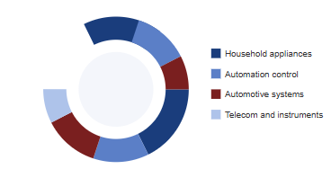
This donut chart is a general illustration of where relay usage tends to concentrate across industries rather than a precise measured survey result. Household appliances take a significant share since many common devices rely on relays to switch heating elements, motors, and pumps safely. Automation control follows closely, covering the control panels and machinery interlocks found throughout industrial facilities. Automotive systems represent another substantial share because vehicles use multiple relays to manage lighting, fuel pumps, and auxiliary motors. Telecommunication and instrument applications make up a smaller but steady share, often relying on relays for signal routing and circuit protection where isolation between control and load circuits is important. This spread illustrates why relay manufacturers typically design several product families rather than a single universal part.
Certification And Quality Testing For Relay Products
Because relays often sit inside safety relevant circuits, certification against recognized standards is an important part of evaluating a relay supplier. Certifications such as UL, TUV, CE, and CQC each involve testing against defined electrical and safety criteria, and compliance with EU RoHS requirements confirms that restricted hazardous substances are not present above defined limits. A relay manufacturer that maintains ISO 9001 quality system certification is following a documented approach to consistent manufacturing quality, which is a useful reference point when comparing suppliers for OEM or ODM cooperation.
About Ningbo Helishun Electron Co Ltd
Ningbo Helishun Electron Co., Ltd was founded in 2000 and is located in Ningbo City on the coastline of the East Sea, covering 8800 square meters of facility space. The company specializes in researching, developing, and producing relays under its registered trademark HELISHUN, and has built a role within the relay market over more than two decades of operation.
The company has introduced advanced technology and testing equipment from home and abroad, supporting a dependable quality management system that has passed ISO 9001:2015 quality system certification. Product characteristics and mounting layouts are kept consistent with comparable international designs, and the company's products have gained certification from UL, TUV, CE, and CQC, while complying with EU RoHS requirements. HELISHUN relays are sold in both domestic and international markets and are widely used in household electrical appliances, telecommunication, automation control, automobiles, and instruments and meters. Customers and partners interested in OEM and ODM cooperation are welcome to reach out to the company directly for further discussion.
A Practical Checklist For Selecting A Relay
Pulling the technical points above together, the following checklist summarizes the specification areas worth confirming before finalizing a relay choice for a new design or a replacement part.
- Confirm coil voltage matches the control circuit output, such as 5V, 12V, or 24V DC.
- Confirm contact rating exceeds the actual load voltage and current with reasonable margin.
- Select the correct contact configuration, NO, NC, or changeover, for the intended default circuit state.
- Include flyback diode protection on DC coil circuits driven by transistors or microcontrollers.
- Match mounting style, PCB, plug in socket, or blade terminal, to the physical installation.
- Check environmental ratings against the expected temperature, humidity, and vibration conditions.
- Verify relevant certifications such as UL, TUV, CE, CQC, and RoHS compliance for the target market.
- Estimate expected switching frequency and compare it against the rated mechanical and electrical life.
Frequently Asked Questions
Q1. How does a relay work in simple terms.
A small control current energizes a coil, which creates a magnetic field that moves an armature to open or close a separate load circuit.
Q2. What is the difference between coil voltage and contact rating.
Coil voltage is the control side voltage needed to energize the relay, while contact rating describes the maximum load side voltage and current the contacts can switch.
Q3. Are electromagnetic relays or solid state relays better for frequent switching.
Solid state relays generally suit applications with very frequent switching cycles since they have no mechanical contacts to wear, while electromagnetic relays remain common for general purpose switching.
Q4. What industries commonly use relays.
Relays are widely used in household electrical appliances, automation control panels, automotive systems, telecommunication equipment, and instrument and meter circuits.
Q5. What is the difference between a normally open and normally closed relay contact.
A normally open contact stays disconnected until the coil is energized, while a normally closed contact stays connected until the coil is energized.
Q6. Why does a relay coil circuit need a flyback diode.
A flyback diode gives the voltage spike created when the coil is de-energized a safe path to dissipate, protecting nearby transistors or microcontroller pins from damage.
Q7. Does Ningbo Helishun Electron Co Ltd offer OEM and ODM cooperation.
Yes, the company welcomes partners interested in OEM and ODM cooperation alongside its standard relay product lines.


