



 English
 中文简体
中文简体Content
- 1 What Does A Relay Do: The Direct Answer
- 2 Relay Meaning And Relay Definition Explained
- 3 How Does A Relay Switch Work Step By Step
- 4 Relay Type Usage Across Common Application Categories
- 5 Mosfet Vs Relay: Choosing Between Electronic And Mechanical Switching
- 6 Typical Contact Current Ratings Across Relay Categories
- 7 Automotive Relay Applications And Common Failure Signs
- 8 Relay Mechanical Life Expectancy Trend Across Switching Cycles
- 9 How To Select The Right Relay For A Circuit
- 10 About Ningbo Helishun Electron Co Ltd
- 11 Frequently Asked Questions About Relays
What Does A Relay Do: The Direct Answer
A relay is an electrically operated switch that uses a small control signal to open or close a separate, often much larger, electrical circuit. In simple terms, what does a relay do comes down to one core function: it lets a low power signal, such as a signal from a sensor, a microcontroller, or a thermostat, safely control a higher power circuit like a motor, a compressor, a heater, or an automotive accessory, without the control circuit ever touching the high power side directly. This isolation is the entire reason relays exist across household appliances, automotive systems, industrial automation panels, telecommunication equipment, and PCB level control boards. Whether the discussion is about an electromechanical relay with a physical coil and moving contacts, or a solid state relay ssr that switches electronically with no moving parts, the underlying purpose remains the same: convert a small trigger into reliable, isolated control of a larger load. The remainder of this guide walks through relay meaning, relay definition, how a relay switch works step by step, the difference between relay and switch, mosfet vs relay comparisons, common relay types, and a full set of frequently asked questions covering practical relay selection and troubleshooting.
Relay Meaning And Relay Definition Explained
The relay definition used across electrical and electronics engineering describes a relay as an electrically controlled device that mechanically or electronically opens and closes one or more sets of contacts in response to a control signal applied to a coil or control input. Put another way, relay meaning centers on the idea of relaying a small signal into a larger switching action, which is also where the word itself originates historically in telegraph and signaling systems. Define relay in electrical terms and you generally arrive at the same core idea: a control input, an isolation barrier, and a switched output. This definition of relay applies equally whether the component is a general purpose relay on a PCB, a high current relay in an industrial panel, or a small signal relay used in low power sensing circuits.
Relay In Electronics Versus Relay In Electrical Systems
Relay in electronics circuit usage typically refers to smaller PCB relay components that switch signal level or low power loads on a circuit board, such as those found inside appliance controllers or communication equipment. Relay in electrical systems, on the other hand, often refers to larger power relay and industrial relay devices used to switch motors, heaters, and three phase equipment. Both categories share the same underlying operating principle, but they differ in contact rating, physical size, mounting style, and the type of control circuitry used to drive them.
How Does A Relay Switch Work Step By Step
Understanding how does a relay switch work requires looking at the two separate sides of the device: the control side and the switched side. On an electromechanical relay, applying voltage to the relay coil generates a magnetic field around an internal electromagnet. This magnetic field pulls a movable armature toward the coil, and that armature is mechanically linked to one or more sets of contacts. As the armature moves, it either closes a normally open contact, opens a normally closed contact, or switches a common contact from one position to another, depending on the relay contact configuration. When the control voltage is removed, a spring returns the armature to its resting position and the contacts return to their original state.
A solid state relay works on a different principle. Instead of a coil and moving parts, a solid state relay ssr uses semiconductor components, commonly a triac, thyristor, or power transistor stage, along with an optical or transformer based isolation barrier between the control input and the switched output. When the control input is energized, the internal semiconductor switch turns on and allows current to flow through the load circuit; when the control input is removed, the semiconductor turns off. Because there are no moving parts, solid state relay high speed switching becomes possible, along with longer expected operating life under high cycle count applications, though solid state devices generally have different thermal and voltage drop characteristics compared with electromechanical designs.
- Control signal is applied to the relay coil or control input terminal
- A magnetic field forms around the coil in an electromechanical relay, or an isolation stage activates in a solid state relay
- The armature moves, or the internal semiconductor switch turns on
- The switched contact set changes state, completing or breaking the load circuit
- Removing the control signal returns the relay to its resting or off state
Relay Type Usage Across Common Application Categories
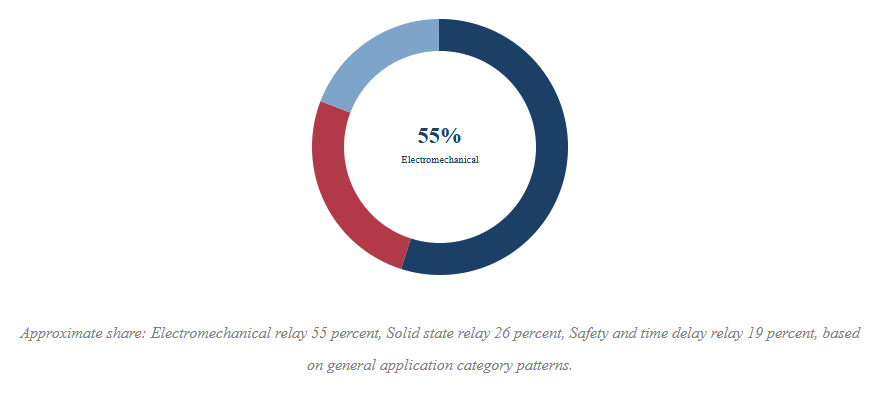
The donut chart below presents a general illustrative breakdown of where different relay categories tend to be applied across typical industrial and consumer electronics use cases. Electromechanical relays remain the largest general category because of their simplicity, wide contact rating range, and long established use in automotive relay, industrial relay, and general purpose relay applications. Solid state relays occupy a meaningful and growing share, particularly in applications requiring high speed solid state relay switching, frequent cycling, or silent operation without mechanical contact wear. Specialty categories, including safety relay and time delay relay products, make up a smaller but important share because these devices serve very specific protective and sequencing functions within control panels. This distribution is illustrative and intended to help readers understand general category proportions rather than represent any single market study.
Relay Vs Switch: What Actually Separates Them
The relay vs switch question comes up often because both devices open and close a circuit path, but the mechanism of control is fundamentally different. A standard mechanical switch, such as a toggle switch or push button, is operated directly by a person physically moving the switch actuator. A relay, by contrast, is operated by an electrical control signal rather than direct human contact, which allows it to be triggered remotely, automatically, or by another electronic circuit such as a microcontroller output pin. This distinction is why relays are described as switches relays in automation contexts, since a relay is technically a switch, but one controlled electrically rather than manually.
This difference matters practically in several ways. A relay can switch a circuit located far from the operator, which is essential in automotive relay wiring where a small dashboard signal controls a high current circuit near the engine bay. A relay can also switch loads that draw far more current than a small control switch could safely handle, since the control side of the relay only needs to supply enough current to energize the coil or control input, while the switched side handles the actual load current through separate, appropriately rated contacts.
Mosfet Vs Relay: Choosing Between Electronic And Mechanical Switching
The mosfet vs relay comparison is common in circuit design discussions because both components can switch a load on and off in response to a control signal, but they behave quite differently in practice. A mosfet relay style circuit, meaning a mosfet used as the switching element rather than an actual relay device, offers fast switching speed, silent operation, and no mechanical wear over time. However, a mosfet as a relay typically has a small but non zero voltage drop across it when conducting, generates heat under sustained load, and generally requires more careful circuit design around gate drive voltage, thermal management, and protection against voltage spikes.
A traditional relay, particularly an electromechanical relay, provides true galvanic isolation between the control circuit and the load circuit, since the contacts are physically separate from the coil circuit. This isolation is valuable in applications where control and load circuits use very different voltage levels or where isolation is required for safety or noise reduction reasons. A solid state relay attempts to combine some benefits of both approaches, offering electronic style silent switching along with an internal isolation barrier, though it does not have the fully mechanical contact separation of an electromechanical relay.
| General comparison between mosfet switching and relay switching characteristics | |||
| Characteristic | Mosfet Switching | Electromechanical Relay | Solid State Relay |
| Isolation Type | None or optical stage added separately | Physical contact isolation | Optical or transformer isolation |
| Switching Speed | Very fast | Moderate, limited by armature movement | Fast |
| Mechanical Wear | None | Present over many cycles | None |
| Audible Click | No | Yes | No |
Typical Contact Current Ratings Across Relay Categories
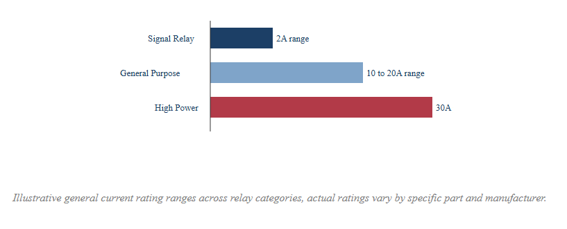
The horizontal bar chart below illustrates typical general contact current rating ranges across common relay categories, from small signal relay devices used on PCB level signal paths, up through general purpose relay and industrial relay products used for motor and heater switching. Signal relays are generally rated for lower current since they are designed to switch low level control or communication signals rather than power loads. General purpose relays cover a wide middle range and are the most commonly specified category for household electrical appliance and automation control applications. High current relay and high power relay categories are built for demanding applications such as motor protection relay circuits and industrial control relay panels, where contact durability under repeated high load switching becomes the primary design consideration.
Different Types Of Relays And Common Contact Forms
Different types of relays are typically classified by both their operating principle and their contact arrangement. On the operating principle side, the major categories include electromechanical relay, solid state relay, and reed relay designs, along with specialty categories such as time delay relay, safety relay, and programmable relay units used in sequencing and protective control applications. On the contact arrangement side, relay contact forms describe how many sets of contacts exist and how they switch, commonly labeled using standard form designations.
Common Relay Contact Forms
- Form A, also called normally open, closes the circuit only when the coil is energized
- Form B, also called normally closed, breaks the circuit only when the coil is energized
- Form C, a changeover contact, switches between two positions and is often called relay no and nc since it provides both a normally open and normally closed path from a common terminal
- DPDT and multi pole configurations switch two or more independent circuits simultaneously from a single coil signal
Specialty Relay Categories
Time delay relay and on delay timer relay products introduce a controlled delay between the control signal being applied and the contacts changing state, which is useful for sequencing motor starts or protecting downstream equipment from inrush conditions. Safety relays are designed specifically for emergency stop circuits and machine guarding applications, often incorporating forced guided contacts so that a welded or stuck contact can be detected rather than silently failing. Phase monitoring relay and voltage monitoring relay devices continuously watch three phase or single phase supply conditions and open a control circuit if voltage, phase sequence, or phase loss falls outside acceptable limits, which helps protect motors and sensitive equipment from abnormal supply conditions.
Automotive Relay Applications And Common Failure Signs
Automotive relay usage is extremely common because vehicles combine many high current circuits, such as headlights, fuel pumps, cooling fans, and starter motors, with relatively low current control signals coming from switches, sensors, and the vehicle control module. A relay in a car allows a small gauge control wire running to the dashboard or steering column to safely trigger a much heavier gauge circuit running directly from the battery to the load, which reduces wiring complexity and voltage drop compared with running full load current through long control wiring.
A burnt relay or burnt out relay is one of the more common automotive electrical faults reported by technicians and hobbyists alike. Typical signs that a relay has failed include a clicking sound with no corresponding load activation, a load that stays on continuously even when it should switch off, or visible discoloration and a melted relay housing caused by sustained overcurrent through undersized contacts. A corroded relay socket, often caused by moisture intrusion in engine bay locations, can also cause intermittent operation that mimics a fully failed relay, which is why checking the socket and connector condition is a standard early diagnostic step before replacing the relay itself.
Relay Mechanical Life Expectancy Trend Across Switching Cycles
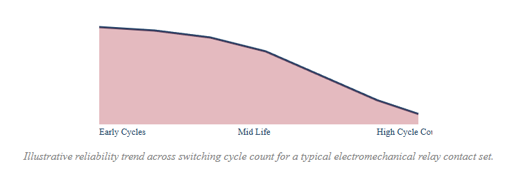
The area chart below illustrates a general trend in expected mechanical reliability for electromechanical relay contacts as switching cycle count increases. Early in a relay life cycle, contact resistance and performance typically remain highly stable, since contact surfaces are clean and spring tension is at its designed value. As switching cycles accumulate, gradual contact wear, minor surface pitting from arcing, and spring fatigue can begin to influence performance, particularly under higher current or inductive load switching conditions. This is one reason solid state relay options are often selected for applications involving very high cycle counts, since semiconductor switching does not experience the same mechanical wear mechanism. The chart reflects a general illustrative pattern referenced from widely published relay engineering literature rather than a specific test result for any single part number.
Relay Suitability Across Common Application Categories
The comparison grid below presents a general suitability view across four common application categories, scored qualitatively rather than with precise numerical data. Electromechanical relays remain highly suitable for general purpose relay, automotive relay, and industrial relay switching where moderate cycle counts and simple coil driven control are sufficient. Solid state relays are particularly well matched to high speed solid state relay applications and situations requiring frequent switching, silent operation, or resistance to mechanical vibration. Safety relays and time delay relay products are purpose built for protective and sequencing functions rather than general load switching, so their suitability is concentrated specifically in machine safety and control sequencing contexts rather than broad general use.
| General suitability overview across relay categories and common application types | |||
| Application Category | Electromechanical Relay | Solid State Relay | Safety Or Time Delay Relay |
| Automotive Circuits | Well suited | Used in specific cases | Limited use |
| High Cycle Automation | Moderate fit | Well suited | Limited use |
| Motor Protection | Well suited | Moderate fit | Well suited |
| Emergency Stop Circuits | Limited use | Limited use | Well suited |
How To Select The Right Relay For A Circuit
Selecting a relay for a given circuit generally starts with identifying the load characteristics, since contact rating must comfortably exceed the expected steady state current and account for inrush current on inductive or motor loads. Coil voltage must match the available control signal, whether that is a low voltage DC signal from a microcontroller, a 12 volt automotive circuit, or a 110 volt relay or 220 volt relay coil driven directly from mains level control wiring. Contact form should match the switching requirement, whether a simple normally open circuit is sufficient or a changeover form C configuration is needed to control two separate circuit states from one coil signal.
Mounting style also matters for practical integration, since a pcb relay soldered directly onto a circuit board suits compact electronic assemblies, while a panel mount relay or din rail solid state relay suits industrial control cabinets where technicians need to access, test, and replace components without desoldering. For applications involving frequent switching or long service life expectations, evaluating solid state relay options alongside traditional electromechanical designs can help match the relay type to the actual duty cycle of the application rather than defaulting to one category by habit.
- Confirm load current and inrush current fall within the contact rating
- Match coil or control voltage to the available control signal source
- Select the correct contact form for the required switching logic
- Choose a mounting style suited to the installation environment
- Consider switching frequency and expected service life when choosing between electromechanical and solid state options
About Ningbo Helishun Electron Co Ltd
Ningbo Helishun Electron Co., Ltd. was founded in 2000 and is located in Ningbo City, on the Grand East port along the coastline of the East Sea. The company covers an area of 8800 square meters and is specialized in researching, developing, and producing relay products, playing an established role within the relay market. Advanced technology and testing equipment introduced from both domestic and international sources support a dependable quality management system throughout production, and the company has passed ISO9001 2015 quality system certification, with product characteristics and mounting layout kept consistent with widely used international relay standards.
Company products have received certification recognition including UL, TuV, CE, and CQC marks, and comply with EU RoHS requirements, supporting use as a priority replacement option in applications requiring similar relay specifications. Helishun relays are sold across domestic and international markets and are widely used in household electrical appliances, telecommunication equipment, automation control systems, automobile electrical circuits, and instrument and meter applications. Guided by a commitment to quality across all levels of management, the company has built strong customer relationships through careful manufacturing practices, and welcomes customers as well as OEM and ODM partners from home and abroad to explore extensive cooperation opportunities.
Frequently Asked Questions About Relays
Q1: What does a relay do in a simple circuit
A relay uses a small control signal to open or close a separate circuit, allowing low power control of a higher power load without direct contact between the two circuits.
Q2: What is the difference between relay and switch
A switch is operated directly by a person, while a relay is operated electrically by a control signal, allowing remote or automatic control of the switched circuit.
Q3: What is the difference between an electromechanical relay and a solid state relay
An electromechanical relay uses a coil and moving contacts, while a solid state relay uses semiconductor switching with no moving parts, generally offering faster and silent operation.
Q4: How do I know if a relay has failed
Common signs include a clicking sound with no load response, a load that will not turn off, or visible discoloration such as a melted or burnt relay housing.
Q5: What does form C mean on a relay
Form C describes a changeover contact that provides both a normally open and a normally closed path from a common terminal, sometimes referred to as relay no and nc.
Q6: Why are relays used in automotive circuits
Relays allow a small control wire from a switch or module to safely trigger a higher current circuit near the load, reducing wiring size and voltage drop in the vehicle.
Q7: What is a time delay relay used for
A time delay relay introduces a controlled delay between the control signal and the contact change, commonly used for sequencing motor starts or protecting equipment from inrush conditions.
Q8: Can a mosfet replace a relay
A mosfet can switch a load electronically without moving parts, but it does not provide the same physical contact isolation as a relay, so the right choice depends on isolation and load requirements.


