

 English
 中文简体
中文简体Content
- 1 Relay Definition and Basic Working Principle
- 2 Internal Components of an Electromechanical Relay
- 3 Main Types of Relays Compared
- 4 Relay Contact Configurations: SPST, SPDT, DPST, DPDT
- 5 Why Relays Matter: Isolation, Amplification, and Safety
- 6 Common Relay Applications
- 7 About Ningbo Helishun Electron Co., Ltd.
- 8 Frequently Asked Questions
A relay is an electrically operated switch that uses a small control signal to open or close a separate, often higher-power circuit. In a traditional electromechanical relay, a coil generates a magnetic field that pulls a movable armature, which then makes or breaks contact with output terminals; in a solid state relay, semiconductor components perform the same switching function without any moving parts. This article explains relay definition, internal components, working principle, the main relay types including electromechanical, solid state, and reed relays, and how to read common relay terminology such as NO, NC, and COM contacts.
Relays exist because many control systems need a small, safe, low-power signal — from a microcontroller, sensor, or switch — to operate a much larger load such as a motor, heater, or lighting circuit. The relay acts as a bridge between the control circuit and the load circuit, providing electrical isolation while allowing one signal to manage another. This guide covers the engineering fundamentals in a structured, reference-style format useful for students, technicians, and procurement engineers evaluating relay options.
Relay Definition and Basic Working Principle
The clearest relay definition describes it as a device with contacts that open and close in response to an input signal applied to a coil. In engineering reference material, a relay is consistently described as a device with contacts that opens and closes a switch as a result of an input signal, voltage or current, applied to a coil. This input-output relationship is what separates a relay from a manual switch: the switching action is triggered electrically rather than by hand.
The working principle is grounded in electromagnetic induction. In general terms, when voltage is applied across the relay's coil, current flows through it, generating a magnetic field, and this electromagnetic force attracts the armature, a movable lever, toward the coil. The movement of that armature is the mechanical event that actually switches the load circuit on or off.
Once the coil is de-energized, a spring returns the armature to its resting position, restoring the contacts to their original state. This cycle, energize, attract, switch, release, repeats reliably across the relay's rated operating life, which is why relays remain a trusted control element across household appliances, automotive systems, industrial automation, and telecommunication equipment.
Internal Components of an Electromechanical Relay
Understanding relay internals helps explain why relays behave the way they do under different loads and conditions. Standard engineering breakdowns identify the core parts as an electromagnet, switching points, mechanically movable contacts, and a spring, with the electromagnet constructed by winding a copper coil around a metal core. Each part plays a distinct role in the switching sequence.
Coil
The coil is the input side of the relay. Current flowing through the coil generates the magnetic field that drives the entire switching action; this is the low-power signal side of the device.
Armature
The armature is the moving lever attracted toward the energized coil. Its movement is what physically opens or closes the relay's contacts, translating an electrical signal into a mechanical action.
Contacts: NO, NC, and COM
Relay contacts are labeled by their resting state. As standard relay construction references describe, the armature is held in place by a spring so that when the relay is de-energized there is an air gap in the magnetic circuit, with one set of contacts closed and the other open. A normally open (NO) contact is open at rest and closes when energized; a normally closed (NC) contact is closed at rest and opens when energized; the common (COM) terminal connects to whichever contact is currently active.
| Component | Location | Function |
|---|---|---|
| Coil | Input side | Generates magnetic field when energized |
| Armature | Mechanical link | Moves under magnetic attraction |
| NO Contact | Output side | Closes when coil energized |
| NC Contact | Output side | Opens when coil energized |
| Spring | Mechanical link | Returns armature when de-energized |
Main Types of Relays Compared
Relays are generally grouped into electromechanical, solid state, and reed designs, each suited to different switching speeds, load currents, and operating environments. Across engineering overviews, the three most commonly used types are consistently identified as electromechanical relays, solid state relays, and reed relays, with electromechanical designs being the most basic and widely used.
Electromechanical Relay (EMR)
An electromechanical relay uses a physical armature and contacts, making it well suited to general purpose switching, automotive circuits, and household appliances. It is durable and cost-effective, though contacts experience mechanical wear over many switching cycles.
Solid State Relay (SSR)
A solid state relay switches electronically using semiconductor components instead of moving parts. In semiconductor relay design, a MOS FET relay is a type of solid state relay that uses power MOSFETs in its output elements, and because it relies on semiconductors the contacts do not mechanically open or close, which reduces footprint, enables quiet operation, and extends operating life. SSRs are favored where fast switching, silent operation, and long service life matter more than raw current-handling capacity.
Reed Relay
Reed relays use two magnetic reeds sealed inside a glass tube. They are commonly described in technical resources as a small, compact, fast operating switch design hermetically sealed in a glass envelope, which makes the contacts unaffected by contaminants, fumes, or humidity. This sealed construction makes reed relays attractive for signal switching applications where contamination resistance is important.
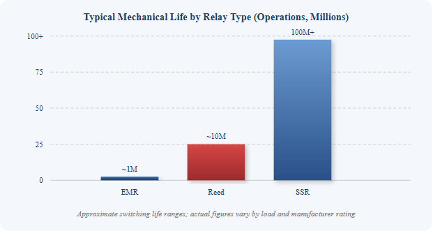 This chart compares the approximate mechanical switching life of the three main relay types on a logarithmic scale. Electromechanical relays typically deliver around one million operations before contact wear becomes significant, consistent with commonly documented ranges of up to 1,000,000 mechanical operations. Reed relays improve on this by roughly an order of magnitude because their sealed, low-friction contact design reduces wear. Solid state relays exceed both because they have no moving parts at all, so their service life is limited by semiconductor thermal stress rather than mechanical fatigue. This comparison is useful when selecting a relay for high-cycle applications such as automation lines or frequent switching control panels.
Relay Contact Configurations: SPST, SPDT, DPST, DPDT
Beyond switching technology, relays are also classified by how many poles and throws their contacts support. The basic distinction is that, with just one pole, SPST relays can control just one circuit and can only exist in an open or closed state, while SPDT relays allow a single pole to swing between two positions, both of which conduct. Double pole versions extend this logic to two independently switched circuits.
- SPST (Single Pole Single Throw) — controls one circuit, either open or closed
- SPDT (Single Pole Double Throw) — one pole switches between two output positions
- DPST (Double Pole Single Throw) — controls two separate circuits, each open or closed
- DPDT (Double Pole Double Throw) — controls two circuits, each switching between two positions
In standard contact-form classifications, DPDT relays consist of two poles where each individual pole has two throws, and these are used for phase or polarity reversal in motor direction control. This makes DPDT configurations especially relevant in motor control circuits, automotive accessory wiring, and applications requiring simultaneous switching of two independent signal paths.
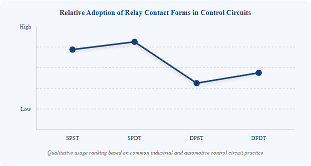
This line chart illustrates the relative prevalence of each contact form in general purpose control circuits, based on common engineering practice rather than a single statistical source. SPDT contacts see the widest use because they provide both a normally open and normally closed path from a single pole, giving designers flexibility without added cost. SPST follows closely as the simplest and most economical option for basic on-off switching tasks. DPDT sits above DPST because dual-circuit, dual-position switching is frequently needed in motor reversing and signal routing applications, while pure dual on-off switching, DPST, is comparatively less common. Engineers selecting a contact form should match the configuration to the actual circuit topology rather than defaulting to the most familiar option.
Why Relays Matter: Isolation, Amplification, and Safety
Relays serve three core engineering purposes that explain their continued relevance in modern circuit design. The core value proposition across applications is consistent: relays allow a low-power signal to control a high-power circuit, making them indispensable in automation, safety systems, and modern electronics. This single property, signal amplification with electrical isolation, underlies nearly every relay application.
It is well established in relay engineering that a small voltage applied to a relay's coil can result in a large voltage being switched by the contacts, which is the practical basis for using relays as interface components between sensitive control electronics and heavier loads such as motors, compressors, or lighting banks.
Safety is the third pillar. Because the control circuit and the load circuit are physically separated inside the relay, a fault or short on the load side does not directly expose the low-voltage control circuit to hazardous conditions. This isolation principle is why relays remain standard practice in automotive starter circuits, industrial control panels, and home automation systems handling mains-level loads.
- Signal isolation between control and load circuits
- Amplification of a small signal into a larger switching action
- Safe remote control of high-voltage or high-current loads
Common Relay Applications
Relays appear across nearly every industry that uses electrical control systems. Typical use cases include home electrical appliances such as refrigerators and washing machines, industrial machinery such as molding equipment and programmable controllers, and plant control panels in chemical facilities and power stations. The breadth of these applications reflects how universally useful the basic switching principle is.
In the automotive sector specifically, relays handle high-current functions such as starter motor engagement, headlight switching, and accessory power management, allowing a small ignition or dashboard signal to control heavy current draw safely. In telecommunications and early computing, relays historically served as signal repeaters and logic elements before solid-state electronics became dominant, a role documented extensively in the history of long-distance telegraph and telephone exchange systems.
About Ningbo Helishun Electron Co., Ltd.
Ningbo Helishun Electron Co., Ltd. was founded in 2000 and is located in Ningbo City, on the coastline of the East Sea, covering a facility of 8800 square meters. The company specializes in researching, developing, and producing relays, and holds an established position in the relay manufacturing sector under its registered trademark.
The company has introduced advanced technology and testing equipment from both domestic and international sources, supporting a dependable quality management system. It has passed ISO9001:2015 quality system certification, and its product characteristics and mounting layouts are kept consistent with comparable international relay designs, supporting straightforward replacement and cross-reference for engineers and buyers.
Ningbo Helishun's relay products have obtained certificates including UL, TUV, CE, and CQC, and comply with EU RoHS requirements. "HELISHUN" relays are sold across both domestic and international markets, and are widely applied in household electrical appliances, telecommunication equipment, automation control systems, automobiles, and instruments and meters.
The company pursues high quality through all-round management and careful manufacturing, aiming to meet customer requirements consistently across general purpose, automotive, and signal relay categories. Ningbo Helishun welcomes customers from home and abroad to visit the company, as well as partners interested in OEM and ODM cooperation for relay products spanning electromechanical and solid state designs.
Frequently Asked Questions
Q1: What is the basic relay definition in electronics?
A relay is an electrically operated switch with contacts that open or close in response to a control signal applied to a coil. It allows a small input signal to control a separate, often larger, circuit.
Q2: What is the difference between a relay and a switch?
A manual switch is operated directly by physical movement, while a relay is operated electrically through a coil and electromagnet. This allows a relay to be controlled remotely by another circuit rather than by hand.
Q3: What is the difference between an electromechanical relay and a solid state relay?
An electromechanical relay uses a physical armature and contacts that move under magnetic attraction, while a solid state relay uses semiconductor components to switch electronically with no moving parts, resulting in quieter operation and longer service life.
Q4: What do NO and NC mean on a relay?
NO stands for normally open, meaning the contact is open until the coil is energized. NC stands for normally closed, meaning the contact is closed until the coil is energized.
Q5: Where are general purpose relays commonly used?
General purpose relays are used in household appliances, automotive systems, industrial control panels, telecommunication equipment, and automation systems, wherever a low-power signal needs to control a separate circuit safely.


")
-1")
-2")
-3")


