



 English
 中文简体
中文简体Content
- 1 What a relay does and why it matters for diagnosis
- 2 Common symptoms of a bad relay
- 3 How to test a relay with a multimeter
- 4 How to test a relay without a multimeter
- 5 Relay pinouts and what the readings mean
- 6 Common failure modes and root causes
- 7 How to choose a replacement relay
- 8 Maintenance practices to extend relay life
- 9 Frequently asked questions about relay diagnostics
- 9.1 How can I tell if a relay is bad without a wiring diagram?
- 9.2 Can a relay click and still be bad?
- 9.3 What ohms reading should a relay coil have?
- 9.4 What does OL mean when testing a relay?
- 9.5 Can a bad relay cause a fuse to blow?
- 9.6 How long should a relay last?
- 9.7 Should I replace all relays when one fails?
- 9.8 Can a relay be repaired instead of replaced?
- 10 How to tell if a relay is bad: a quick five-point checklist
When a motor stops turning, a compressor stops cycling, or a bank of headlights suddenly goes dark, the first reaction is usually to blame the expensive component. Experienced technicians know that the relay in the control circuit deserves attention first, because relays sit exactly between low-power control logic and high-power loads. Learning how to tell if a relay is bad before ordering costly replacement parts or opening a wiring harness can save both time and money. The fastest diagnostic sequence is to observe the controlled load, listen for the relay click, measure coil resistance across the energizing pins, and then verify contact continuity across the load pins with a multimeter. Most relay failures fall into four predictable groups: an open coil, a shorted coil, welded contacts, or high-resistance contacts caused by arcing and contamination. Each group produces distinct symptoms and specific multimeter readings, so a structured test leads to a confident diagnosis in minutes.
What a relay does and why it matters for diagnosis
A relay is an electromagnetic switch. Inside the housing, a coil of insulated wire is wound around a magnetic core. When current flows through the coil, the core becomes magnetized and pulls a movable armature. The armature carries a contact bridge that either connects or disconnects two stationary contacts. In a normally open (NO) relay, energizing the coil closes the circuit; in a normally closed (NC) relay, energizing the coil opens it. Single-pole double-throw (SPDT) relays combine both functions: a common terminal switches between a normally open terminal and a normally closed terminal.
This separation between the control side and the load side is the reason relays are found everywhere in automotive electrical systems, industrial control panels, household appliances, HVAC equipment, and telecommunications gear. The control circuit only needs enough current to energize the coil, while the load circuit can draw dozens of amps through the contacts. A 12V DC coil with 80 ohms of resistance, for example, draws only about 150 milliamps, yet its contacts can switch a 30A load. Because the relay physically isolates the two circuits, it also protects sensitive controllers from the electrical noise generated by motors, solenoids, and lamps.
Understanding this structure is the foundation of relay diagnostics. Every test performed on a relay is really a check of either the coil or the contacts. If the coil is open, the armature never moves and the relay does nothing. If the contacts are welded or contaminated, the relay may click correctly while still failing to control the load. Real-world conditions such as voltage spikes, arcing from inductive loads, humidity, dust, and vibration can shorten the service life that a relay manufacturer originally designed into the component. A relay that fails early is rarely a random event; it is usually the result of an application condition that exceeded the relay's rated limits.
Common symptoms of a bad relay
A failing relay rarely announces itself with a single universal sign. The symptoms depend on which internal part has failed. The most frequently reported symptoms, in rough order of frequency, are:
- The controlled component does not turn on at all even though the control signal is present.
- The relay clicks audibly, but the load does not energize.
- The relay is silent when the control circuit is activated.
- The load operates intermittently or drops out when the equipment vibrates.
- The load stays energized and cannot be switched off.
- The relay housing shows melting, discoloration, or a burnt smell.
Each symptom points to a different internal fault. No click at all usually means the coil circuit is open or the coil has no supply voltage. A click with no load output points to the contact side, whether that is a mechanically broken contact, a burnt contact surface, or a corroded terminal. Intermittent operation often indicates a weakened armature spring, a pitted contact set, or a relay that has suffered mechanical wear over millions of cycles. A load that stays on when the control signal is removed is the classic signature of welded contacts, a condition frequently caused by high inrush current from motors or capacitive loads. Visible signs of overheating mean the relay has been carrying more current than its contact rating allows, or the coil has been exposed to sustained overvoltage, and the unit should be replaced even if it still passes a basic continuity check.
Field failure statistics are not identical across every industry, but they consistently point to the same dominant causes. The distribution below summarizes what control engineers and maintenance teams typically see when failed relays are returned for analysis. Coil-related failures account for roughly one in every three returns. Contact problems, including welding, pitting, and surface contamination, make up most of the remaining cases. Mechanical wear, terminal corrosion, and rare internal short circuits complete the picture.
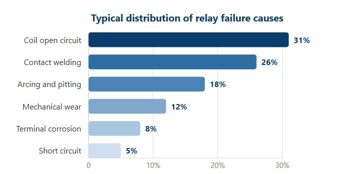
The ratio between coil failures and contact failures matters because it tells you which test to perform first. When roughly one third of bad relays have an open or shorted coil, a simple resistance check across the energizing pins catches the largest single failure group in seconds. Contact welding is the second most common problem, and it behaves differently: the relay may show correct coil resistance while the load circuit stays permanently energized. Arcing damage develops gradually over the relay's life. Every time the contacts open under load, a micro arc forms between the poles. Under inductive loads such as motors, solenoids, or clutch coils, that arc erodes the silver-alloy contact surface. Repeated erosion produces blackened spots, pitting, and eventually a rough surface that cannot conduct current reliably. Mechanical wear becomes more relevant in relays that see millions of operations, because the armature spring weakens and the contact gap drifts. Terminal corrosion is more common in automotive and outdoor equipment exposed to humidity, road salt, or vibration. Knowing this distribution helps you decide whether to spend time on coil testing or contact testing first. For any relay that fails the click test or reads outside the expected coil resistance range, replacement is almost always more economical than repair. Even a relay with a functioning coil should be replaced if its contacts show more than approximately one ohm of resistance under load.
| Symptom observed | Likely internal fault | Quick confirmation test |
|---|---|---|
| No click, load dead | Open coil, or no coil supply | Measure ohms across coil pins; expect OL for open coil |
| Click, but load stays off | Pitted, burnt, or contaminated contacts | Energize coil, measure resistance between COM and NO |
| Load stays on continuously | Welded NO contacts | Check continuity between COM and NO while relay is unpowered |
| Intermittent operation | Weak armature spring, partial contact erosion | Cycle the relay ten times and watch the load behavior |
| Burnt smell or melted housing | Overcurrent, overvoltage, or coil burnout | Visual inspection plus coil resistance check |
How to test a relay with a multimeter
A digital multimeter is the most reliable tool for answering how to tell if a relay is bad. Multimeters are inexpensive, widely available, and capable of testing both the coil and the contact side of any relay. The procedure below works for automotive relays, PCB-mount relays, and industrial socket relays alike. You need a multimeter with resistance mode and ideally a continuity beeper; a small 12V battery or bench supply for the energized contact test is also useful.
Before you start
Remove the relay from the vehicle or panel before testing. Testing a relay while it is still connected to the circuit produces false readings because other components create parallel current paths. If you are working under the hood, disconnect the negative battery terminal first. Next, identify the pin layout. Automotive relays generally follow the ISO 7588 standard: pins 85 and 86 are the coil, pin 30 is the common contact, pin 87 is the normally open contact, and pin 87a is the normally closed contact on five-pin versions. Industrial socket relays, such as the 8-pin DPDT or 11-pin 3C formats, have the coil and contact groups marked on the housing or in the manufacturer's data sheet. When the markings are faded, use the wiring diagram printed on the relay socket or trace the circuit with a continuity tester.
Coil resistance test
Set the multimeter to resistance mode, usually indicated by the ohm symbol or the word OHMS on the dial. Touch the probes to the two coil pins, pins 85 and 86 on an automotive relay or the dedicated coil terminals on an industrial relay. The multimeter will display the coil resistance. A healthy DC coil on most power and automotive relays reads between 50 and 120 ohms. Small PCB relays, especially telecom types, can read higher, and large contactor-style relays can read lower. The important comparison is against the nominal coil resistance published by the relay manufacturer. A reading of zero indicates a shorted coil, meaning the insulation between turns has broken down. A reading of OL, which stands for open loop or over limit, means the coil wire is broken and the relay is definitely dead.
An open coil is one of the most common relay failures. It usually results from prolonged overvoltage, a short circuit in the control wiring, or metal fatigue where the fine coil wire meets the terminal pin. When the meter shows OL, no further coil testing is needed. The relay cannot pull the armature in, so it cannot switch any load, and the only correct action is replacement.
Contact continuity test
After the coil test, check the contacts. With the relay removed from the circuit, the normally closed contact should show continuity. Touch one probe to pin 30 and the other to pin 87a on a five-pin relay. A reading near zero ohms means the NC contact is intact. The normally open contact, pin 87, should read OL while the relay is unpowered because the contacts are physically separated. If pin 87 shows continuity with the relay unpowered, the contacts are welded shut, which explains why the load stays on permanently.
To test the normally open contact properly, energize the coil. Apply the rated coil voltage to pins 85 and 86. A 12V relay can be energized from a car battery, a 12V power supply, or a bench supply; a 9V battery will pull in most 12V relays because the minimum pickup voltage is usually about 75 percent of the rated value. When the coil is energized, you should hear a click, and the resistance between pins 30 and 87 should drop to near zero. If the coil clicks but the resistance stays at OL, the NO contact set is damaged. If the reading is a few ohms instead of near zero, the contacts are contaminated or pitted and will cause voltage drop and heat under load.
Voltage drop test
A resistance reading alone does not always reveal a marginal contact. A contact that measures 0.3 ohms on the meter may still drop several volts when carrying 20 amps. The voltage drop test is the most realistic way to assess contact health. With the relay installed and the load operating, set the multimeter to DC volts and place the probes across the relay contacts, one probe on pin 30, the other on pin 87. A healthy relay contact should drop less than 0.2 volts. If the voltage drop exceeds 0.5 volts, the contacts are degraded and will generate heat that accelerates further failure. This test is especially valuable in automotive starting and charging circuits, where a bad relay can cause slow cranking, dim lights, or intermittent operation even though the relay still clicks.
Full bench test procedure
A complete bench test combines the coil and contact tests into one repeatable sequence.
- Record the coil resistance between the coil pins and compare it with the rated value.
- Apply the rated coil voltage and listen for a crisp click.
- With the coil energized, measure the resistance between the common and NO pins. It should be below 0.2 ohms.
- With the coil energized, measure the resistance between the common and NC pins. It should read OL, because the NC contact is open.
- Remove coil power and repeat steps 3 and 4 in the opposite state: NC closed, NO open.
- Cycle the relay at least ten times to confirm that the click is consistent and the contact resistance is stable.
This bench test reveals nearly every common failure mode. A relay that clicks but fails step 3 has bad contacts. A relay that fails step 2 has a coil problem or a mechanically stuck armature. A relay that passes all six steps can be reinstalled with confidence. For critical applications, repeat the test with the relay warmed to its normal operating temperature, since some marginal relays fail only when hot.
How to test a relay without a multimeter
If a multimeter is not available, a relay can still be evaluated with two basic methods: the click test and the swap test. Both are used daily by automotive technicians and are perfectly acceptable for a preliminary diagnosis. They will not catch every marginal failure, but they will identify the majority of dead relays.
The click test
Remove the relay and apply the rated coil voltage across the coil pins using a battery and two short test wires. For a 12V automotive relay, a car battery works; for a 24V industrial relay, use two 12V batteries in series or a bench supply. A healthy relay produces a distinct, crisp click as the armature moves. No click means the coil is open, the armature is jammed, or the applied voltage is too low to pull the armature in. A weak or muffled click can indicate a partially shorted coil, a weakened return spring, or mechanical binding in the hinge. Note that the click test does not verify the contacts at all. A relay can click perfectly while its contacts are burned to the point of no conduction, so a click alone is never enough to declare a relay good.
The swap test
The swap test compares the suspect relay with a known-good unit of the same type and pinout. Replace the suspect relay with the known-good relay and operate the circuit. If the load works, the original relay is bad. If the load still fails, the fault lies elsewhere: in the control signal, the fuse, the wiring, or the load itself. The swap test is fast and requires no electrical measurements, but it depends on having a matching spare on hand. When swapping, confirm that the replacement has the same coil voltage, contact form, and pin arrangement. Installing a 5-pin relay where a 4-pin relay belongs, or a 24V coil in a 12V circuit, will produce misleading results and can damage the replacement.
Both methods have clear limitations. The click test does not verify contact conductivity, and the swap test only works when the spare relay is guaranteed good. For a definitive answer, a multimeter test is recommended whenever one is available. If neither tool is on hand, a temporary jumper wire across the load contacts can confirm whether the load itself is functional, but this should be done with caution because it bypasses the protection and control logic that the relay provides.
Relay pinouts and what the readings mean
Relay manufacturers publish pinouts for every model, and understanding the pin layout is half of the diagnostic process. The table below shows common relay configurations and the electrical readings to expect from a healthy unit. The pin numbers follow the industry conventions used on most automotive and industrial relays.
| Relay format | Pin count | Coil pins | Contact pins | Typical coil resistance |
|---|---|---|---|---|
| 4-pin automotive (SPST-NO) | 4 | 85, 86 | 30, 87 | 50 to 120 ohms |
| 5-pin automotive (SPDT) | 5 | 85, 86 | 30, 87, 87a | 50 to 120 ohms |
| Mini PCB SPDT relay | 5 | 2 coil pins | COM, NO, NC | 70 to 150 ohms |
| 8-pin DPDT (socket mount) | 8 | 2 coil pins | 2 sets of COM, NO, NC | 70 to 120 ohms |
| 11-pin 3C (socket mount) | 11 | 2 coil pins | 3 sets of COM, NO, NC | 70 to 120 ohms |
| 14-pin 4C (socket mount) | 14 | 2 coil pins | 4 sets of COM, NO, NC | 70 to 120 ohms |
Coil resistance by itself is not a pass-or-fail criterion. It becomes meaningful when compared with the rated value printed by the relay manufacturer. A deviation of more than 15 percent from the nominal coil resistance suggests winding deterioration. A completely open coil reads OL, and a shorted coil reads near zero. Contact resistance, by contrast, should be as close to zero as possible. New relays typically carry a guaranteed contact resistance below 0.1 ohm, and many manufacturers specify 0.05 ohm or less for silver-alloy contacts. A measured resistance above 0.5 ohm on a used relay is a warning sign, and above 1 ohm is a practical reason to replace the relay, especially in power circuits where even one ohm of contact resistance at 10 amps creates 10 volts of drop and 10 watts of heat.
The coil polarity on standard DC relays does not matter for most automotive and general-purpose types. The relay will pull in regardless of whether positive or negative is connected to pin 85 or pin 86. The exception is polarized relays, which contain internal steering diodes or electronic drivers and must be wired with the correct polarity. If the relay housing shows a diode symbol or the data sheet specifies polarity, follow it exactly. AC coil relays, common in industrial 110V or 220V control circuits, have the same pin layout as DC versions but require AC voltage of the rated frequency; testing them with DC can damage the coil.
When working with socket-mounted relays, the readings at the socket terminals should match the readings at the relay pins. If the relay measures healthy but the socket terminals show an open coil, the fault is in the socket, the wiring, or a loose terminal. This distinction saves time and prevents replacing a good relay for a wiring problem.
Common failure modes and root causes
Knowing how to tell if a relay is bad also means understanding why relays fail. Different failure modes have different root causes, and identifying the root cause prevents the replacement relay from failing the same way in a few weeks.
Open coil
An open coil is the electrical equivalent of a broken wire. The coil circuit has a physical gap, so no current can flow and the armature never moves. Overvoltage causes the coil wire to overheat and melt; vibration can fatigue the fine coil wire right at the terminal junction; and in humid environments, corrosion can eat through the coil termination. Open coils are easy to detect because the relay is silent and the coil resistance reads OL.
Shorted coil
A shorted coil has reduced resistance between the coil pins, often near zero, because the insulation between turns breaks down and adjacent turns touch. The relay may pull in weakly or not at all. A shorted coil can also draw excessive current from the control circuit, overheating the driver transistor or the fuse protecting the coil. An out-of-range low resistance reading on the coil pins confirms this failure, and the relay should be replaced immediately to protect the control electronics.
Welded contacts
Contact welding happens when the contacts carry a heavy inrush current and then separate slowly enough for the metal to melt and fuse together. Motors, capacitive loads, and incandescent lamps all have high inrush currents, making them the most common causes of welded contacts. The relay clicks normally, but the load stays permanently connected. Measuring continuity between the common and NO pins with the relay unpowered shows near-zero resistance, exactly as if the contacts were closed. Do not attempt to pry welded contacts apart; the contact surfaces are damaged, and the relay should be replaced.
Pitted and contaminated contacts
Arcing across the contacts during every switching cycle slowly transfers metal from one contact to the other. The surface develops craters and blackened spots, reducing the effective contact area and increasing resistance. High resistance means more heat, and more heat accelerates further oxidation. Silicone contamination from adhesives, sealants, or lubricants inside the equipment can also form an insulating layer on the contacts. The result is a relay that clicks but delivers reduced voltage to the load, often causing the load to run at reduced performance or to fail intermittently. This failure mode is especially common in DC circuits because DC arcs are more persistent than AC arcs, which self-extinguish at the zero crossing of the sine wave.
Mechanical wear
After hundreds of thousands of operations, the armature spring weakens, the hinge wears, and the contact gap changes. The relay may click faintly, may be slow to drop out, or may chatter when the coil is energized. Mechanical wear is more common in relays cycled frequently, such as those in flasher circuits, industrial counters, or HVAC staging controllers. A relay that has exceeded its mechanical endurance rating, typically one to ten million operations depending on the design, should be replaced on a preventive maintenance schedule rather than after failure.
Terminal and pin corrosion
Corrosion at the terminal pins is frequently misdiagnosed as a relay failure. Road salt, humidity, and condensation can create a high-resistance oxide layer on the pins and in the socket. The relay itself may be perfectly healthy, but the connection between the relay and the socket is compromised. Measuring the same resistance at the socket terminals rather than at the relay pins reveals this condition. Cleaning the socket terminals and applying a dielectric grease rated for electrical contacts often restores normal operation without replacing the relay.
Practical field troubleshooting for these scenarios is covered in more detail in the article on relay common problems and handling measures, which is listed in the further reading section at the end of this guide.
How to choose a replacement relay
Once the diagnosis confirms a bad relay, the next step is selecting a replacement. Matching the electrical and mechanical specifications is critical. A careless replacement can fail within days or damage the circuit it feeds.
Match the coil voltage and contact rating
The coil voltage must match the control circuit. Common DC coil ratings are 5V, 9V, 12V, 24V, and 48V; common AC ratings are 110V and 220V. Installing a 24V coil in a 12V circuit will not pull the armature in reliably, while a 5V coil in a 12V circuit will overheat the coil and may burn it out in minutes. The contact rating must also match the load current. Use the relay's rated contact current for the specific load type, not just the steady-state current. Inductive loads such as motors and solenoids require a contact rating roughly three to five times the steady-state current because of inrush and back-EMF arcing. Resistive loads such as heaters are easier, but they still generate a cold inrush that can reach ten times the running current in some heating elements.
Match the contact form and mounting style
When the replacement is intended for a control panel or an appliance, the contact form must also match. The three most common forms are SPST-NO (single pole, normally open), SPDT (single pole, double throw), and DPDT (double pole, double throw). An application that needs to switch two independent circuits requires a DPDT relay; using two SPST relays as an improvised DPDT is possible but adds wiring complexity and introduces a second point of failure. The replacement must also fit the existing socket or board layout. Relays are available in PCB pin, quick-connect, plug-in socket, and panel-mount formats. A relay manufacturer like HELISHUN designs each product family so that the pin arrangement matches industry-standard socket patterns, which is why the 8-pin DPDT and 11-pin 3C formats are interchangeable across many brands. Before ordering, confirm the pin pitch, terminal type, and mounting dimensions.
4-pin and 5-pin formats, 25A to 80A, PCB or quick-connect terminals, sealed against dust and moisture. General power relays
SPDT and DPDT, 5A to 30A, PCB pin or quick-connect, transparent or opaque housings, socket-compatible versions available. Telecom relays
Low-current signal switching, 2A to 3A, PCB mount, compact footprint for communication modules. Relay sockets
DIN-rail and panel-mount sockets for 8-pin, 11-pin, and 14-pin relays, with screw or quick-connect terminals.
Work with a reputable relay manufacturer or supplier
Quality varies significantly across relay suppliers. A relay with a weak contact spring, thin coil wire, or poor sealing will fail quickly even if the data sheet looks identical. When purchasing replacement relays for production or maintenance stock, work with a relay manufacturer that can provide UL, TUV, CE, CQC, and RoHS compliance documentation and stable production quality. OEM and ODM options allow custom coil voltage, terminal shape, and packaging to be specified for volume orders. Wholesale buyers should verify the manufacturer's production history, factory area, quality system, and export experience before committing to a long-term supply agreement.
For small appliance control boards and instrumentation, a compact PCB relay is usually the correct replacement. The SPDT 5-pin 7A/10A mini power relay covers the common 10A class used in household appliances, HVAC control boards, and general instrumentation.
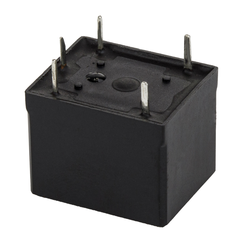 Custom mini power relay T73 PCB Relay Suppliers, FactoryHelishun Electron Co.,Ltd is China Custom hot selling SPDT 5PIN 7A 10A mini power relay T73 PCB PIN HLS8 Suppliers and OEM Factory, CONT...View Product →
In vehicles, the coil and contact ratings are the first details to check before ordering. The 5-pin 40A automotive relay suits headlights, horns, cooling fans, and auxiliary loads that need 40A switching capacity with either PCB or quick-connect installation.
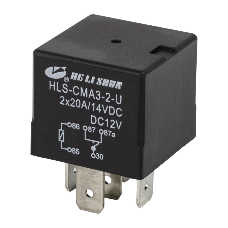 Custom hot selling 5PIN 40A automotive relay PCB QUICK PIN HLS-CMA3 Suppliers, OHelishun Electron Co.,Ltd is China Custom hot selling 5PIN 40A automotive relay PCB QUICK PIN HLS-CMA3 Suppliers and OEM Factory, CONTACT...View Product →
For industrial control panels, socket-mounted DPDT relays offer easier replacement and maintenance. The transparent 8-pin 2C 10A power relay is a direct socket-compatible replacement for the widely used 8-pin DPDT format, and it pairs with standard relay sockets for quick wiring in control cabinets. Socket-mounted relays should be paired with a properly rated relay socket from the same product family; a standard 8-pin socket with screw terminals simplifies wiring and lets you replace the relay without cutting or disconnecting any wires.
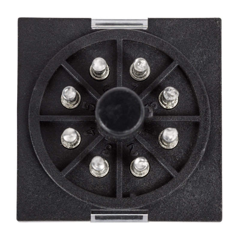 Custom transparent 8PIN 2C 10A power relay HLS-MK2P Suppliers, OEM Factory - NinHelishun Electron Co.,Ltd is China Custom transparent 8PIN 2C 10A power relay HLS-MK2P Suppliers and OEM Factory, CONTACT DATA : Contact...View Product →
Maintenance practices to extend relay life
Replacing a failed relay is only half of the job. Adjusting the conditions that caused the failure, where possible, will extend the life of the new relay. Two factors dominate: the environment and the application.
Environmental controls
Heat is the single biggest enemy of relay life. Every 10 degrees Celsius increase in ambient temperature roughly halves the thermal life of the coil insulation and accelerates contact oxidation. Keep relays away from heat sources, allow airflow around the housing, and use a relay with a higher temperature rating in hot compartments. Humidity and corrosive gases attack both the coil terminations and the contact surfaces. Enclosed relays and sealed automotive relays resist moisture better than open-frame types. In dusty environments, a sealed relay prevents abrasive particles from entering the contact chamber and wearing down the silver-alloy surfaces.
Application conditions
The load type matters more than most maintenance schedules assume. Inductive loads create arcs when the contacts open, and those arcs erode the contact material. Adding a flyback diode across the load for DC circuits, or a snubber network for AC circuits, can reduce arcing dramatically. The coil side also benefits from protection: a suppression diode across the coil prevents the voltage spike that occurs when the coil is de-energized, which protects both the driving transistor and the relay itself. Finally, ensure that the relay is not cycled more frequently than its rated life allows. If an application needs millions of operations per year, consider a relay with a higher mechanical endurance rating or switch to a solid-state relay for the high-cycle portion of the circuit.
| Factor | Effect on relay | Recommended response |
|---|---|---|
| Ambient temperature above 70 degrees Celsius | Coil insulation degrades, contact oxidation accelerates | Choose a high-temperature relay, add airflow or shielding |
| Humidity and condensation | Terminal corrosion, coil wire failure at the pins | Use sealed relays or apply conformal coating on the PCB |
| Dust and airborne particles | Abrasive wear of contacts, clogged armature hinge | Use dust-tight housings and IP-rated relays in dirty areas |
| Inductive load without arc suppression | Contact erosion, welding, reduced contact force | Install flyback diodes or RC snubbers across the load |
| Frequent switching above 10 cycles per minute | Mechanical fatigue, spring weakening | Select a relay with high mechanical endurance or move to solid-state |
Frequently asked questions about relay diagnostics
How can I tell if a relay is bad without a wiring diagram?Look for the pin markings on the relay housing or the socket. Most relays print the pin numbers directly on the case, and sockets often have a small diagram. If no markings exist, use the coil resistance to identify the coil pins: the coil pins are the pair that reads between 50 and 150 ohms on most relays, while the contact pins read OL from each other. Then apply the rated voltage to the coil pins and listen for the click. |
Can a relay click and still be bad?Yes. The click only proves that the coil is pulling the armature in. The contacts may be pitted, burnt, contaminated, or welded, preventing them from conducting current correctly. Always test contact continuity after confirming the click, and check the NO and NC states in both energized and de-energized conditions. |
What ohms reading should a relay coil have?Most automotive and general-purpose DC relays have a coil resistance between 50 and 120 ohms. Small PCB and telecom relays can read from 70 to 150 ohms or higher. The exact value depends on the coil voltage and power rating; always compare the measured value with the nominal resistance printed in the relay's data sheet. A deviation of more than 15 percent from nominal indicates deterioration. |
What does OL mean when testing a relay?OL stands for open loop or over limit. In resistance mode, it means the meter cannot measure a closed path, so it displays the maximum value. Across the coil pins, OL means the coil wire is broken. Across normally open contacts with the relay unpowered, OL is the correct result because the contacts should be open. |
Can a bad relay cause a fuse to blow?Normally a relay does not blow the fuse protecting the load circuit. A shorted coil can blow the fuse in the control circuit, and a welded or arcing contact can allow an overcurrent condition that clears the load fuse. If a fuse blows repeatedly, check the relay contacts and the load itself, not just the relay coil. |
How long should a relay last?A well-designed electromagnetic relay rated for a typical load should operate for 100,000 to 1,000,000 cycles, depending on the load type and switching frequency. Mechanical endurance can reach tens of millions of operations, but contact life under load is usually shorter. In automotive use, relays commonly survive the life of the vehicle when properly selected. In industrial applications, a relay that fails before 10,000 operations points to a selection or environment problem. |
Should I replace all relays when one fails?Replacing only the failed relay is usually sufficient if the other relays show no signs of wear. In critical systems where a failure causes downtime or safety risk, consider replacing relays that have been in service for more than 80 percent of their expected life. Some maintenance programs replace all relays of the same batch during scheduled downtime, because relays from the same production lot can share the same manufacturing weakness. |
Can a relay be repaired instead of replaced?Relays are generally not repairable. Opening the housing damages the seal, the contact gap is factory-set, and replacement contacts are not available as service parts. Attempting to file down pitted contacts or bend the armature spring may restore function temporarily, but the relay will fail again quickly and can be a safety hazard. Replacement is almost always cheaper and more reliable than repair. |
How to tell if a relay is bad: a quick five-point checklist
The entire diagnostic process condenses into five steps that take less than ten minutes to complete. Keep this checklist in mind the next time you need to determine how to tell if a relay is bad:
- Observe the controlled component. If it does not run, does not change state, or stays on permanently, the relay is a prime suspect.
- Listen for the click. Energize the coil with the rated voltage and confirm that the armature moves.
- Measure the coil resistance. Compare the reading with the rated nominal value and reject the relay if it reads OL, zero, or more than 15 percent off.
- Measure the contact resistance in both states. Expect near zero ohms on a closed contact and OL on an open contact.
- Perform a voltage drop test under load when the circuit permits. Replace the relay if the drop exceeds 0.5 volts.
Following these steps in order, a bad relay can be confirmed or cleared quickly. A relay that fails any of the checks should be replaced with a properly matched component from a reliable relay manufacturer. Do not reuse a relay that has been subjected to visible overheating, welded contacts, or a burnt smell, even if it happens to pass one or two of the tests. The margin between a partially working relay and a completely failed relay is often very small, and a relay that tests marginal in the workshop will fail at the worst possible moment in the field.
Further reading and technical support
- For a deeper explanation of the internal mechanics, read about the working principle of an electromagnetic relay.
- For additional field scenarios and corrective actions, review the article on relay common problems and handling measures.
- If you need help selecting the right relay part number or want to discuss OEM and wholesale requirements, contact HELISHUN for relay sourcing and technical assistance.


