



 English
 中文简体
中文简体Content
- 1 What a Contact Relay Symbol Represents on a Schematic
- 2 Contact Forms Behind the Symbol: SPST, SPDT, DPST and DPDT
- 3 Reading NO and NC States in a Contact Relay Symbol
- 4 What the Symbol Does Not Tell You: Contact Ratings by Relay Family
- 5 From Symbol to Pinout: 5-Pin, 8-Pin, 11-Pin and 14-Pin Relays
- 6 Application Scenarios and Selection Points for B2B Buyers
- 7 Common Mistakes When Interpreting Contact Relay Symbols
- 8 Maintenance, Handling and Bench Verification
- 9 FAQ: Contact Relay Symbol Questions from Engineers and Buyers
- 9.1 What three things does a contact relay symbol tell you at a glance?
- 9.2 How do I tell the NO contact from the NC contact in the symbol?
- 9.3 Why do SPDT and DPDT symbols look so similar?
- 9.4 Does a 5-pin relay always match a Form C contact relay symbol?
- 9.5 Do IEC and ANSI drawings use different contact relay symbols?
- 9.6 Can I approve a replacement relay by matching the symbol alone?
- 10 Related Resources from HELISHUN
Two quotations arrive for what looks like the same 5-pin relay. Both parts share the same footprint, the same 12 VDC coil and a similar contact rating, yet on one datasheet the movable contact is drawn hanging away from its terminal, and on the other it is drawn resting against it. The first relay keeps a lamp circuit dead at rest; the second keeps it live. That single difference in the contact relay symbol is why purchasing teams, design engineers and quality inspectors all need to read schematic drawings fluently before they approve a supplier.
Here is the short version for anyone who needs the answer now: a contact relay symbol carries three pieces of decision-grade information. It shows how many separate contact sets the device has (its poles), what each contact does at rest (normally open or normally closed as drawn), and which terminal is common to each contact set. Read those three things correctly and most relay selection, replacement and wiring errors disappear; read them carelessly and you can order a functionally opposite part that still fits the same socket.
This guide explains how relay contact symbols are drawn under the conventions engineers actually meet on datasheets, how each contact form maps to real pin counts, what the symbols deliberately leave out, such as current, voltage and load type, and how to close those gaps with datasheets and bench checks. The examples reference the product families built by Ningbo Helishun Electron Co., Ltd. (HELISHUN), a relay manufacturer established in 2000 whose SPDT, DPDT and multi-pole lines cover telecom, general power and automotive applications.
Key takeaway: a contact relay symbol tells you the pole count, the resting state of each contact and the common terminal - master those three details and most ordering mistakes never happen.
What a Contact Relay Symbol Represents on a Schematic
The honest starting point is that a relay symbol is a contract, not a picture. It agrees that the physical part will behave in a specific electrically controlled way: when the coil receives enough voltage, the armature moves and every contact attached to it flips state. The symbol itself separates into two electrically independent halves, because that independence - galvanic isolation between the control circuit and the load circuit - is the entire reason relays exist.
The coil half of the symbol
Control-side drawings differ by convention. IEC-style schematics, common in Europe and Asia, draw the coil as a plain rectangle. North American drawings more often use a zigzag or looped coil mark, and many machine-tool diagrams show a long box marked with the letter J beside or inside it. Reference designators such as K, KA or J sit next to the coil, and the rated coil voltage - 5 VDC, 12 VDC, 24 VDC, or 230 VAC for larger industrial types - is written alongside. When you compare a HELISHUN datasheet against a schematic, this annotation is what tells you which coil version to order, because an otherwise identical relay body is sold with different coil voltages.
The contact half of the symbol
Load-side symbols use a movable blade drawn against or away from a fixed terminal. A normally open (NO) contact shows a visible gap: the blade hangs at an angle and touches nothing when the relay rests. A normally closed (NC) contact shows the blade drawn onto the fixed terminal, usually at a slight angle, indicating continuity at rest. A changeover contact - the single most common industrial form, also called Form C or SPDT - draws one movable blade positioned between two fixed terminals, sharing one common terminal (COM) that lands on either side depending on coil state.
The dashed line that ties them together
A dashed line runs between the coil and the contacts on a correctly drawn symbol. That line is the mechanical linkage: it reminds the reader that one physical armature drives all the contact sets together, while carrying no electrical connection at all. It is also the visual cue that every contact on that relay changes state simultaneously, which matters when you are sequencing two circuits with one coil signal.
Key takeaway: a contact relay symbol is two electrically separate halves - a coil and one or more contacts - joined only by a dashed mechanical linkage, and the drawing always shows the de-energized condition.
Contact Forms Behind the Symbol: SPST, SPDT, DPST and DPDT
Every contact relay symbol you will meet in procurement reduces to two words: poles and throws. Poles count how many separate contact sets move together; throws count how many terminals each set can connect to. Combine the two and you get the four forms that cover nearly all industrial relays - SPST, SPDT, DPST and DPDT - plus the multi-pole 3PDT and 4PDT versions used in control cabinets.
Form designations give the same information a second way. Form A means a normally open contact, Form B means normally closed, and Form C means changeover - one contact that opens here and closes there. A 5-pin automotive or power relay is the textbook Form C device: two coil pins, one COM, one NO and one NC. An 8-pin DPDT is simply two Form C sets sharing one coil.
| Contact form | Form name | Terminals (contacts plus coil) | What the symbol shows | Typical job |
|---|---|---|---|---|
| SPST, one pole, one throw | Form A or B | 2 plus 2 = 4 | One blade against or away from one fixed terminal | Simple on-off load switching |
| SPDT, one pole, two throws | Form C, changeover | 3 plus 2 = 5 | One blade between two fixed terminals over a shared COM | Choosing between two loads, NO and NC logic |
| DPST, two poles, one throw | Double Form A or B | 4 plus 2 = 6 | Two blades moving together, each with one fixed terminal | Switching two lines at once, such as both AC poles |
| DPDT, two poles, two throws | Double Form C | 6 plus 2 = 8 | Two changeover blade groups on one linkage | Motor direction reversal, dual-circuit changeover |
| 3PDT and 4PDT | Three or four Form C sets | 9 or 12 plus 2 = 11 or 14 | Three or four blade groups on one linkage | Control cabinets switching several circuits at once |
Form A - SPST, normally open
One blade drawn open. It closes when the coil pulls in. Four pins including the coil. The classic simple on-off switch.
Form B - SPST, normally closed
One blade drawn closed. It opens when the coil pulls in. Four pins including the coil. Used where the circuit must conduct at rest.
Form C - SPDT, changeover
One blade, two landing points. The classic 5-pin relay that selects between an NO and an NC path through one COM.
Two Form C sets - DPDT
Two changeover blades moving together on one coil. The classic 8-pin relay for two circuits switched in step.
Seeing the form on a real part cements the lesson. The HLS14F1L in our general power range, for example, is a 5-pin SPDT 10 A PCB relay whose pinout matches the Form C symbol exactly - two coil pins on one side and a COM, NO and NC trio opposite - so a technician can verify the schematic against the physical part with a multimeter in under a minute.
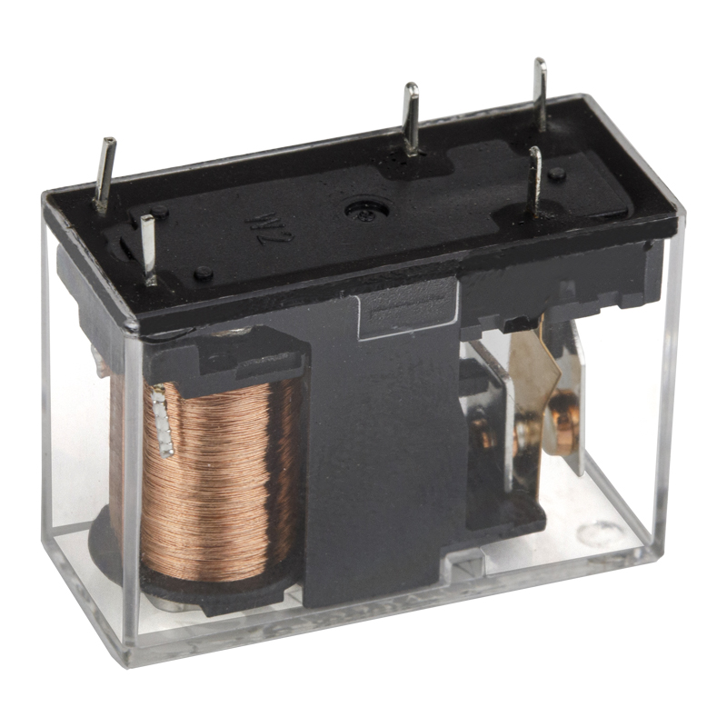 HLS-14F1 5-Pin SPDT 10 A PCB Power RelayThis 5-pin SPDT 10 A relay matches the Form C schematic symbol pin-for-pin, with two coil pins opposite a COM, NO and NC trio, making it easy to verify against a drawing with a multimeter.View Product →
Larger cabinets scale the same idea upward rather than changing it. The transparent 11-pin 3C and 14-pin 4C types in the 13F and 4453 series stack three or four Form C sets on a common coil, which is why their symbols show three or four identical blade groups tied to one dashed linkage line.
Key takeaway: poles and throws define the symbol - SPDT (Form C) with its 5 pins is the industry workhorse, and every larger multi-pole relay is simply more Form C sets moving on one coil.
Reading NO and NC States in a Contact Relay Symbol
The most consequential fact about these drawings is also the one people forget under deadline pressure: the contacts are always drawn in the de-energized state. The symbol shows the relay at rest, coil off, sitting in the warehouse or just powered down. Anything you trace through a drawn-closed contact is live the moment the board powers up, before the control logic does anything at all.
| Coil condition | NO contact | NC contact | Form C: COM lands on |
|---|---|---|---|
| De-energized (as drawn) | Open - no continuity | Closed - continuity | NC terminal |
| Energized | Closed - continuity | Open - no continuity | NO terminal |
That resting-state rule is the backbone of fail-safe design. An emergency-stop lamp, a door interlock or an over-temperature alarm is deliberately wired through an NC contact, so a severed coil wire, a missing control supply or a burned-out relay forces the circuit into its alarm state instead of silently switching it off. Brake circuits on conveyors and hoists follow the same logic: power loss must produce braking, not coasting. When you review a schematic, every NC contact you see should raise the question of what the designer wanted to guarantee at rest.
Be equally careful with the word normally. It means the coil is at rest, not that the condition is normal during operation. A relay that spends most of its working life energized - a compressor run relay, for instance - still draws its NO contact open on the schematic, because the drawing documents the de-energized machine, not the running one. Misreading that convention flips the logic of an entire control circuit and ranks among the most frequent faults we see in relay-related field returns.
Key takeaway: the symbol always shows the coil-off state, so a drawn-closed (NC) contact conducts as soon as the system powers up - which is exactly why safety circuits are built on NC contacts.
What the Symbol Does Not Tell You: Contact Ratings by Relay Family
The contact relay symbol describes switching logic, not switching capability. Two drawings can look identical on paper while one contact is rated for 2 A and the other for 80 A. That is why sourcing teams pair the schematic reading with the datasheet rating before any supplier is approved. The chart below maps the typical maximum switching current of the main relay families in the HELISHUN range, from the smallest telecom parts to the heaviest automotive types. Treat it as a field guide from symbol family to expected contact capability, then confirm every figure on the individual datasheet.
Typical Maximum Contact Current by Relay Family
Representative ratings from the HELISHUN product families
Telecom relays (2 to 3 A)
Mini PCB power relays, T73 series (7 to 10 A)
General power relays, T72 and 14F series (10 to 16 A)
High-power relays, T90 and T91 series (30 A)
Standard automotive relays (40 A)
High-current automotive relays (80 A)
Bar length is proportional to maximum contact current, with the 80 A automotive class set as full scale. Confirm exact values on each product datasheet.
Three trends stand out once the bars are in view. First, current capacity climbs by roughly an order of magnitude as you move from telecom parts to automotive ones, which is why the same SPDT symbol can describe a 2 A signal switch and a 40 A load switch. Second, terminal style changes with the rating: the 2 to 3 A telecom relays and the 7 to 10 A mini T73 parts use fine PCB pins, while the 30 A T90 and T91 types and the 40 to 80 A automotive families move to quick-connect tabs that carry heat and cable weight away from the board. Third, pole count expands in the middle of the range, where the transparent 13F, 4453, MK2P and MK3P series offer one to four poles at 5 to 20 A, because control cabinets need multi-circuit switching more often than they need raw current.
For procurement teams, the chart carries three practical lessons. A symbol match is never a product match, and approving a substitute without checking its ampere rating is how a 5 A signal relay ends up switching a 12 A heater. Resistive ratings do not transfer to inductive loads, since motor inrush can reach five to six times running current and weld contact tips sized only for the steady state. Certification evidence should follow the rating claim, because the UL, TUV, CE and CQC marks carried across the range exist precisely so a wholesaler or OEM buyer can verify that the printed 30 A was proven rather than assumed. Coil voltage belongs in the same conversation, since a perfectly matched contact form at the wrong coil voltage will never pull in. Where a project mixes loads, many buyers split circuits across two relay families instead of oversizing one part, keeping both cost and failure energy down. Finally, ask prospective suppliers for load-life curves at your actual load current, not just the headline number, and file those curves with the schematic so the next qualification starts from evidence.
Key takeaway: identical symbols can hide a forty-fold difference in contact rating, so pair every symbol reading with a datasheet ampere check and a derating review for inductive loads.
From Symbol to Pinout: 5-Pin, 8-Pin, 11-Pin and 14-Pin Relays
Translating a drawn symbol into a physical part is where theoretical understanding meets the production floor. The schematic never shows pin numbers, so the datasheet terminal diagram has to bridge the gap - and pin counting has conventions worth memorizing. A 5-pin relay is almost always SPDT: two pins for the coil, plus COM, NO and NC on the contact side. Automotive parts commonly carry DIN-style numbering, with 85 and 86 on the coil, 30 as the common, 87 as NO and 87a as NC, while PCB power relays use the numbered layout shown in their footprint drawing.
Six-pin parts deserve a caution. Depending on the family, six pins can mean a DPST-NO relay (four contact pins plus two coil pins) or an SPDT with a doubled terminal, so never back-calculate the contact form from the pin count alone. Eight pins reliably indicate DPDT (six contact terminals plus two coil pins), eleven pins indicate 3PDT, and fourteen pins indicate 4PDT, which is why those three counts dominate the transparent multi-pole series.
| Total pins | Contact form | Contact terminals | Coil terminals | Representative HELISHUN series |
|---|---|---|---|---|
| 5 | SPDT, one Form C | 3 | 2 | T72, T73, T90, T91, 14F1L |
| 8 | DPDT, two Form C | 6 | 2 | 14F3L, MK2P 8-pin 2C, 13F2 |
| 11 | 3PDT, three Form C | 9 | 2 | 13F3, MK3P, 4453 11-pin |
| 14 | 4PDT, four Form C | 12 | 2 | 13F4, 4453 14-pin |
The 8-pin DPDT layout is easy to verify in practice. Take the HLS14F3L, an 8-pin DPDT 5 A PCB power relay: its footprint drawing shows the two coil pins at the bottom and two vertical columns of COM, NO and NC above, so each column mirrors the single Form C blade group drawn in the schematic. Lining the datasheet print against the schematic takes seconds and removes nearly all risk of a mirrored or rotated assembly.
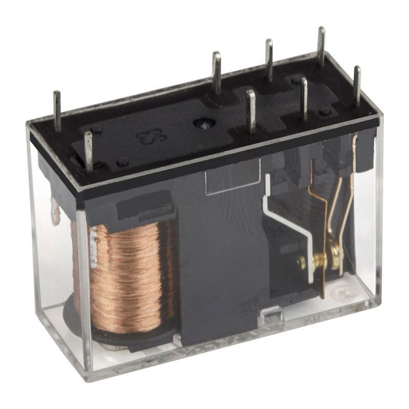 HLS-14F3L 8-Pin DPDT 5 A PCB Power RelayThe HLS14F3L illustrates the 8-pin DPDT layout: two coil pins at the bottom and two COM, NO, NC columns above, letting assemblers check the datasheet footprint against the schematic in seconds.View Product →
Plug-in relays add one more layer. Series built for sockets - the 13F, 4453, MK2P and MK3P families - wire the installation to the socket rather than soldering to the relay, so the schematic symbol stays identical while the cabinet gains tool-free replacement. The socket you choose must match both the pin count and the pin layout, which is why manufacturers list sockets per series instead of selling one universal base.
Key takeaway: pin counts are a strong hint - 5 pins means SPDT, 8 means DPDT, 11 means 3PDT, 14 means 4PDT - but the datasheet terminal diagram, not the count, is the final authority.
Application Scenarios and Selection Points for B2B Buyers
Contact relay symbols repeat across industries, but the selection criteria behind them change with the load. The table below pairs the four verticals where relays do most of their switching work - the same verticals HELISHUN serves with its product lines - and the checks that matter most during supplier qualification.
| Application scenario | What to verify on the symbol and datasheet |
|---|---|
| Home appliance control boards | Compact SPDT symbols; confirm 7 to 10 A ratings, PCB pin terminations, and a coil voltage that matches the board supply |
| Industrial control cabinets | Multi-pole symbols from DPDT to 4PDT; confirm socket pairing, quick-connect versus PCB pins, and visible contact indication where useful |
| Automotive electrical systems | DIN-numbered terminals 30, 87, 87a, 85 and 86; confirm 25 to 80 A ratings, quick-connect tabs, and vibration and temperature tolerance |
| Telecom and instrumentation | Low-current SPDT symbols; confirm 2 to 3 A signal ratings, low and stable contact resistance, and long electrical life |
From the buying side, the symbol is also a communication tool with your supplier. When an RFQ states SPDT Form C, 5-pin PCB, 12 VDC coil, 10 A resistive, a relay manufacturer can respond with an exact series and a footprint drawing, while a vague request for the same as the sample invites substitution risk. Buyers sourcing at wholesale volume should confirm three practical points with any prospective supplier: which certificates back each rating (UL, TUV, CE, CQC), whether installation layouts match the international series the schematic was drawn around, and what the manufacturer's OEM and ODM process looks like for custom coils or terminal styles. HELISHUN has run its own factory in Ningbo since 2000 under an ISO 9001 quality system, with product lines whose installation layouts deliberately track common international footprints - a meaningful advantage when a replacement must drop into an existing PCB without redesign.
Where panels benefit from visible state confirmation, transparent-housing types earn their place. The HLS13F4, a 14-pin 4-pole 10 A relay with a transparent case, lets a maintenance technician watch all four armature blade groups move against the schematic in real time - a small feature that shortens commissioning and fault-finding noticeably in dense control cabinets.
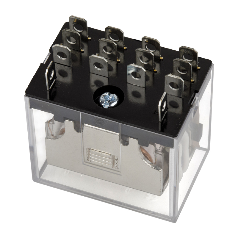 HLS-13F-4 14-Pin 4C 10 A Transparent RelayA 14-pin 4-pole 10 A relay with a transparent case, this part lets maintenance staff watch all four armature blade groups move in real time, speeding commissioning and fault-finding in control cabinets.View Product →
Key takeaway: state the contact form, pin count, coil voltage and load current in the RFQ itself - precise symbol language shortens supplier response and removes substitution risk.
Common Mistakes When Interpreting Contact Relay Symbols
Most relay-related problems trace back to a handful of reading errors rather than to bad components. The following list collects the mistakes we see most often, together with the reason each one matters.
- Treating the drawn state as the energized state. The symbol shows the coil at rest, so wiring a control circuit as if the drawn-closed contact waits for a signal is the classic logic inversion.
- Confusing poles with throws. SPDT and DPDT differ by one pole, but they switch completely different circuit counts - count the blade groups, not the size of the drawing.
- Assuming all 5-pin relays are identical. Coil voltage, terminal style (PCB pin versus quick-connect) and contact rating can all differ within the same form.
- Back-calculating the contact form from pin count. Six-pin parts in particular split between DPST-NO and SPDT variants depending on the family.
- Ignoring the load type behind the rating. A 10 A resistive rating does not cover a 10 A motor start; inrush and inductive loads need derating.
- Forgetting the coil side of the symbol. Most miniature relays are specified to pull in at around 70 to 80 percent of nominal voltage at best, and chronic undervoltage causes chattering and welded contacts.
- Skipping flyback protection. A DC coil driven by a transistor needs a flyback diode across the coil; the schematic will often show it, and omitting it shortens driver life.
Key takeaway: nearly every symbol-related failure comes from reading state, pole count or load type carelessly - a short review checklist catches them all.
Maintenance, Handling and Bench Verification
Relay reliability starts before installation. Contacts stored in humid or sulfur-bearing air grow oxide and sulfide films that raise contact resistance, so relays should stay in their original packaging in a dry, temperature-stable store, and long inventory rotations should favor sealed types where the environment cannot be controlled. A quick continuity check against the symbol filters out most storage casualties before they ever reach a PCB:
- COM to NC shows continuity, and COM to NO shows none, exactly as the symbol is drawn.
- Coil resistance falls within the datasheet band for the ordered coil voltage.
- Energizing the coil at rated voltage produces a clean, single pull-in click and flips both readings.
During assembly, treat terminals as mechanical parts, not just electrical ones. Wave-soldering profiles should follow the datasheet temperature and time limits, hand soldering should stay within the stated iron temperature and duration, and no side force should be applied to sealed relay cases while leads cool. For plug-in types, seat the relay fully into its socket and confirm socket grip, because a loose socket produces intermittent contact that no schematic review will ever reveal.
In service, the failure modes to watch mirror the symbol itself. Chattering or buzzing points to undervoltage or a weak drive circuit; a load that never switches points to a welded or oxidized contact set; a coil that stays cold points to an open coil rather than a contact fault. Transparent-housing relays let you watch the armature answer these questions visually, and keeping one spare per contact form in the drawer turns fault-finding into a two-minute swap test.
Key takeaway: verify against the symbol at three checkpoints - on the goods-in bench, after soldering and during field diagnosis - and most relay faults announce themselves early.
FAQ: Contact Relay Symbol Questions from Engineers and Buyers
What three things does a contact relay symbol tell you at a glance?The pole count - how many separate contact sets move together; the resting state of each set - normally open or normally closed as drawn; and the common terminal for each set. Everything else, such as ratings and coil voltage, comes from the datasheet rather than the drawing. |
How do I tell the NO contact from the NC contact in the symbol?Look at where the movable blade rests in the drawing. A blade hanging with a visible gap from its fixed terminal is NO; a blade drawn touching its fixed terminal is NC. On a changeover symbol, the shared COM sits between the two and lands on the NC side at rest. |
Why do SPDT and DPDT symbols look so similar?A DPDT symbol is simply two SPDT blade groups stacked and tied to the same dashed linkage line, because one coil drives both poles. Count the blade groups: one means SPDT with five pins on a typical part, two means DPDT with eight. |
Does a 5-pin relay always match a Form C contact relay symbol?A 5-pin power or automotive relay is nearly always Form C - two coil pins plus COM, NO and NC. The safe habit is still to confirm with the terminal diagram, because numbering conventions differ between automotive DIN numbering and PCB footprints. |
Do IEC and ANSI drawings use different contact relay symbols?The contacts are drawn in essentially the same blade-and-terminal style everywhere; the coil is where conventions differ, with IEC drawings favoring a rectangle and North American drawings a zigzag or loop. Reference letters also vary by region - K, KA or J - so read the coil annotation rather than relying on one house style. |
Can I approve a replacement relay by matching the symbol alone?No. The symbol proves the switching logic, but approval also needs the coil voltage, the contact rating against your real load type, the terminal style, the footprint, and the certificates your market requires. Matching the symbol is step one of qualification, not the whole process. |
Key takeaway: if a question is not answered by the symbol itself, it is answered by the datasheet - and both should be on file before a purchase order is released.
Related Resources from HELISHUN
For readers who want to keep going, two pages from our own site extend the topics above - one explaining how SPDT contacts behave in practice, and one browse page covering the general power relay families referenced throughout this guide. Both are useful companion material when you are checking a drawing against a real part.
Types of SPDT relays and how they work
General power relay range from HELISHUN
Key takeaway: the fastest way to internalize contact symbols is to read one more explanation and then hold a real 5-pin relay in your hand.
A contact relay symbol is small, but it is the exact point where a design intention becomes a purchasing line item. Read the blade position for state, count the blade groups for poles, find the shared terminal for COM, and then step deliberately into the datasheet for everything the symbol cannot say. Engineers who work that way order the right relay the first time, and suppliers who document their parts that way - with clear terminal diagrams, honest ratings and current certificates - are worth keeping. If you are qualifying a new relay source or replacing a discontinued part, the engineering team at HELISHUN welcomes drawing reviews, sample requests and OEM or ODM inquiries from buyers in more than one hundred countries.
Key takeaway: treat the symbol as a contract covering state, poles and common - then confirm ratings and certifications in the datasheet before releasing the order.


