



 English
 中文简体
中文简体Content
- 1 What Is an Emergency Stop Relay?
- 2 How Does an Emergency Stop Relay Work?
- 3 Types of Emergency Stop Relays
- 4 Key Specifications and How to Select an Emergency Stop Relay
- 5 Emergency Stop Relay vs. Standard Power Relay
- 6 Application Scenarios and Selection Points
- 7 Wiring, Installation, and Practical Compliance
- 8 Maintenance and Troubleshooting
- 9 Emergency Stop Relay FAQ
- 10 Related Resources and Support
When someone presses the red mushroom-head emergency stop button on a production machine, the control system has one job: remove power from the hazardous motion and keep it removed until a deliberate reset takes place. An emergency stop relay is the safety component that supervises that command and switches the machine's enabling circuits through monitored, force-guided contacts. It is not a standard relay that happens to be wired into a stop button. The internal architecture, the failure behavior, and the declared response time are all designed around one requirement: the load must be disconnected even if a contact welds or a wiring fault develops.
This guide explains what an emergency stop relay is, how it works, what types are available, and which specifications matter when you select one. It also covers wiring and reset practices, maintenance and troubleshooting, and a detailed comparison with standard power relays. The goal is to help design engineers, panel builders, maintenance technicians, and purchasing teams make confident decisions for new machines and for replacement of older safety circuits.
If you are not familiar with safety-related control technology, the most important idea is this: an emergency stop relay is part of a safety function, not just a switching device. Standards such as ISO 13849 and IEC 62061 judge the whole chain - button, relay, contactors, and monitoring - as a system. Selecting a relay with the right performance level, contact configuration, and reset behavior is therefore as important as the quality of the stop button itself.
The key takeaway: an emergency stop relay is a monitored safety component, and it cannot be replaced with a general-purpose relay when human safety depends on the circuit.
What Is an Emergency Stop Relay?
An emergency stop relay, often called an e-stop safety relay, is a control device that receives signals from one or more emergency stop command devices and safely disconnects the machine's power contactors, drives, or valves when a stop is requested. In its simplest form, it contains two or more input terminals connected to normally closed contacts of an e-stop button and a set of normally open output contacts that enable the main power circuit. When the button is pressed, the input circuit opens, a logic engine inside the relay opens the output contacts, and the machine loses power.
The word "safely" is what separates this component from an ordinary relay. A standard relay can fail with welded contacts, broken springs, or a stuck armature, and the failure may not be detected until the next emergency. An emergency stop relay is designed so that such faults either prevent the safety function from failing or force the system into a fail-safe state. This is achieved with redundant channels, cross-monitoring of inputs, and force-guided contacts.
Standards play a large role in this market. ISO 13850 defines the requirements for emergency stop function, while ISO 13849-1 and IEC 62061 set the performance and integrity levels used to certify safety-related parts of control systems. An emergency stop relay is typically rated for performance level PL d or PL e, or for Safety Integrity Level SIL 2 or SIL 3, depending on the model.
From a practical viewpoint, the relay performs three distinct tasks. First, it evaluates both channels of the e-stop button and detects short circuits or cross-wiring. Second, it controls the enabling circuit with force-guided contacts that cannot leave a load energized if the relay itself fails. Third, it provides a status or feedback loop that tells the machine controller whether the e-stop function is ready, tripped, or requires reset.
In a modern cabinet, the emergency stop relay may be a slim module with screw terminals, a plug-in relay with a socket, or part of a larger safety controller. The physical format matters less than the internal behavior. The relay must open the enabling contacts within a predictable time, must prevent restart when a fault is detected, and must allow a safe, intentional reset procedure.
An emergency stop relay can also monitor more than a single button. Many models accept two or more e-stop buttons wired in series, as well as protective door switches and light curtain outputs. This makes the same relay suitable for access guards and perimeter protection. When additional output contacts are needed, expansion modules can be added, extending the number of enabling circuits without changing the safety performance of the original function.
Understanding these basics helps explain everything else in this guide. Selection starts with the safety rating, but the practical work is in the contact count, the reset mode, the terminal style, and the way the relay fits into the panel and the machine's control architecture.
Key conclusion: an emergency stop relay is a redundant, monitored switching device whose outputs are held off in a fail-safe manner, defined by standards such as ISO 13849 and IEC 62061.
How Does an Emergency Stop Relay Work?
To choose and maintain an emergency stop relay correctly, it helps to understand its internal operating sequence. A typical dual-channel e-stop relay has the following parts:
- Two or more input circuits connected to the normally closed contacts of the emergency stop button or to safety switch outputs.
- A logic unit that processes both input signals and checks that they switch together within a valid time window.
- A set of force-guided output contacts, usually multiple normally open contacts for the enabling circuits and normally closed contacts for monitoring.
- A reset input that can be configured for automatic or manual reset behavior, often with edge detection.
- An internal power supply and status indicators that show the ready, tripped, and fault states.
The operating cycle works as follows. When power is applied, both input channels must be closed and consistent. The relay signals "ready" and its output enabling contacts close. This is the normal running state. When the emergency stop button is pressed, both channels open. The logic unit detects that the input voltage disappeared on both channels while the relay was in the enabled state, and it opens the enabling contacts immediately. Because the contacts are force-guided, the normally closed monitoring contacts are guaranteed to move to the opposite state at the same time.
After the e-stop command, the relay remains latched in the off state even if the button is released. The operator must perform a deliberate reset - pressing a separate reset button, or switching the reset input - before the enabling contacts can close again. This manual reset prevents a machine from restarting on its own after a stop and forces the user to check the hazardous area first.
Force-guided contact construction is the heart of the design. In a force-guided relay, also called a positively driven relay, all contact blades are mechanically linked to a single drive frame. If one set of contacts cannot open because of welding, the other sets are prevented from closing. This is exactly the behavior a monitoring circuit needs. The normally closed monitoring contacts tell the controller: "the enabling contacts are really open." If the enabling contact welds, the monitoring contacts cannot close, and the controller sees a fault instead of a ready state.
Dual-channel monitoring is equally important. The two input channels are wired so that a short circuit between them will be detected. After both edges switch, the relay performs a self-test and compares the timing of the two channels. If one channel is missing or the timing is wrong, the relay locks out or fails safe.
Some relays add input delay, short-circuit detection, or cross-fault monitoring to satisfy the requirements of ISO 13849-1 Category 3 or 4 architecture. When selecting a relay, you should check whether the declared architecture matches your risk assessment. A relay certified for Cat 4 / PL e, for example, tolerates any single fault and detects it without losing the safety function.
The response time of an emergency stop relay is the interval between the moment the input contacts change state and the moment the output contacts open. Typical values range from 10 ms to 50 ms. This is fast enough for most machines, but it is a declared parameter that must be considered when the stop time of the machine is calculated for the safety distance of light curtains or guards.
Reset modes deserve special attention. Automatic reset means the relay re-closes output contacts as soon as the input conditions are satisfied. Manual reset requires a rising edge on the reset input after the inputs are closed. Monitored reset adds the requirement that the reset signal is only valid when it appears and disappears under controlled conditions, preventing a stuck reset button from keeping the circuit ready.
For engineers who work with force-guided relays from different manufacturers, the operating principle is consistent. What changes is the internal test logic, the number of channels, the supply voltage, and the way the relay reports its state. These differences matter most when replacing a relay or expanding an existing safety system.
Key conclusion: the combination of force-guided contacts, dual-channel input monitoring, and deliberate reset is what makes an emergency stop relay fail safe instead of merely switching off.
Types of Emergency Stop Relays
Emergency stop relays are not a single product category. They vary by function, construction, number of channels, and terminal style. Choosing the wrong format can double the cost of a cabinet or make maintenance unnecessarily difficult.
By function
- Instantaneous safety relays open their enabling contacts directly when the e-stop input is activated. They are the standard choice for most fixed-speed machines.
- Time-delay safety relays add an adjustable delay on energization or de-energization. They are used when a controlled stop, such as a frequency inverter ramp-down, must finish before power is removed.
- Expansion safety relays provide additional enabling contacts driven by the main safety relay. They increase the number of contactor circuits that can be controlled without changing the safety category.
- Door and guard monitoring relays combine emergency stop input with dual-channel door switch monitoring for interlocked guards.
By construction and mounting
The physical format affects panel layout and spare parts management. Compact one-piece relays are the most common and are mounted on DIN rails. Modular systems allow the main relay to be combined with expansion modules. Slim relays reduce space in tight cabinets. Some relays are designed to be plugged into sockets, which makes replacement fast and reduces wiring errors.
By input channel configuration
Single-channel emergency stop relays are used for lower-risk applications or where redundancy is provided elsewhere. Dual-channel relays are the de facto standard for most industrial machines because they detect short circuits and wire breaks in the e-stop loop. The number of channels also affects the wiring diagram: dual-channel wiring requires both a normally closed contact from the button and a second path that can be a second contact or a separate switch.
By terminal style
Screw terminals are traditional and easy to tighten with standard tools. Spring-cage terminals speed up wiring and resist vibration. Plug-in terminals allow the relay housing to be removed for replacement without disconnecting wires. In dusty or corrosive environments, a relay with protected terminals and a sealed housing may be necessary.
When planning a cabinet, we recommend listing the number of channels, output contacts, terminal style, and required width before contacting a supplier. This avoids the common problem of buying a safety relay with the right PL rating but the wrong contact arrangement for the contactor load.
Key conclusion: select the emergency stop relay format after defining function, channel count, mounting, and terminal style; otherwise, safety performance alone is not enough to guarantee a good fit.
Key Specifications and How to Select an Emergency Stop Relay
Selecting an emergency stop relay involves more than checking the performance level on the datasheet. The relay must match the supply voltage of the control circuit, have enough output contacts for all the devices that must be disconnected, and provide the reset behavior your safety procedure requires. The table below summarizes the parameters that appear on most datasheets and the typical values you will encounter.
| Parameter | Typical range | Selection note |
|---|---|---|
| Supply voltage | 24 V DC, 110 V AC, 230 V AC | Match the control voltage; 24 V DC is most common. |
| Input channels | 1 or 2 | Dual-channel is required for high-risk applications. |
| Output contacts | 2 to 8 NO, 1 to 4 NC | The NC contacts are only for monitoring. |
| Contact rating | 4 A to 10 A at 230 V AC | Contactors usually draw less than 2 A per coil. |
| Response time | 10 ms to 50 ms | Include this in stop-time and safety-distance calculations. |
| Reset mode | Automatic, manual, monitored | Manual or monitored reset is required in most standards. |
| Safety level | PL d / SIL 2, PL e / SIL 3 | Review your risk assessment before choosing. |
| Housing width | 22.5 mm to 45 mm | Slim relays save space in dense cabinets. |
| Terminal type | Screw, spring, plug-in | Consider vibration and maintenance frequency. |
Before the chart below, a few words about demand patterns. Machine builders choose emergency stop relays based on the categories of machinery they produce, not on generic preferences. The share of demand across industries is useful when you are assessing a supplier's experience or forecasting spares inventory. The distribution shown here reflects typical patterns seen in industrial control panel manufacturing and machine safety retrofits. It is a planning aid, not a market study.

The bar chart shows a typical distribution of emergency stop relay demand across industrial sectors. Machine tools account for the largest share at roughly 26 percent, which matches the high density of e-stop buttons on lathes, milling machines, presses, and machining centers. Automotive manufacturing follows at about 18 percent, driven by transfer lines, assembly stations, and robot cells where every work station needs its own monitored stop circuit. Packaging machinery is close behind at 15 percent, because wrapping, filling, and cartoning machines run at high speed with frequent product jams and operator access. Robotics and material handling applications represent around 12 percent, and this share is growing as collaborative and mobile robots are integrated into existing production lines. Food and beverage equipment contributes about 10 percent, with washdown requirements pushing demand for sealed or protected relay housings. The remaining 19 percent is spread across textiles, printing, woodworking, construction equipment, and general automation. For a relay manufacturer or wholesaler, this pattern explains why standard relays and sockets for 24 V DC control circuits are the most requested items in safety-related panels. For a machine builder, the distribution is a reminder that specifying common formats and voltages reduces procurement lead times. The practical takeaway is that emergency stop relay selection is heavily influenced by industry-specific requirements such as ingress protection, ambient temperature, and the number of stop buttons connected in series. It also explains why product lines emphasize dual-channel versions with 24 V DC coils and DIN-rail housings.
Once the application context is clear, the actual selection can follow a simple checklist. First, confirm the safety integrity level and category from the risk assessment. Second, choose the number of input channels and decide whether you need feedback monitoring of the contactors. Third, count the output contacts needed to disconnect all hazardous energy sources. Fourth, define the supply voltage and terminal style. Fifth, choose the reset mode according to the operating procedure of the machine. Finally, check the ambient temperature, vibration, and ingress protection ratings.
A good practice is to review established relay selection precautions before placing an order, especially when the same relay will be used in multiple machine types. The same selection rules apply to the auxiliary relays that support the safety circuit, such as a high-power relay for a control load that is not part of the safety function.
Key conclusion: match the relay's safety level, channel count, output contacts, and reset mode to the risk assessment and machine operation procedure; only then consider dimensions and price.
Emergency Stop Relay vs. Standard Power Relay
The most common mistake in panel design is replacing an emergency stop relay with a standard power relay of similar contact rating. The two components look alike and sometimes share the same socket, but their behavior under fault conditions is completely different. The following comparison explains the practical differences.
| Feature | Emergency stop relay | Standard power relay |
|---|---|---|
| Contact construction | Force-guided, mechanically linked | Conventional, independent contacts |
| Failure detection | Monitors weld and wire-break faults | None; failure may go undetected |
| Input circuits | Redundant, cross-monitored | Single coil input |
| Reset behavior | Latched, manual or monitored reset | Immediate re-energization |
| Safety certification | PL / SIL rated | UL / TUV listed but not safety-rated |
| Switching speed | Declared response time | Typical but not guaranteed |
| Cost | Higher, justified by safety | Lower, suited for general loads |
| Typical use | Emergency stop loops, guard monitoring | Control signals, auxiliary loads |
The table shows that the added cost of an emergency stop relay buys three things. First, it buys a guaranteed switching state: the enabling contacts cannot stay closed when one of them is welded. Second, it buys a declared response time that a safety engineer can use in calculations. Third, it buys formal certification that connects the component to the performance level of the machine's safety function. None of these characteristics can be verified on a general-purpose relay.
It is equally important to see where standard relays remain appropriate. The safety relay handles the emergency stop function, but the same panel often contains dozens of auxiliary control relays that switch indicators, cooling fans, heaters, brake release coils, and interlocks outside the safety loop. For these non-safety loads, a robust power relay with a high contact rating is the right choice. In high-current applications such as switching a 30 A heating load or a motor contactor coil, a heavy-duty relay provides long service life and simple replacement.
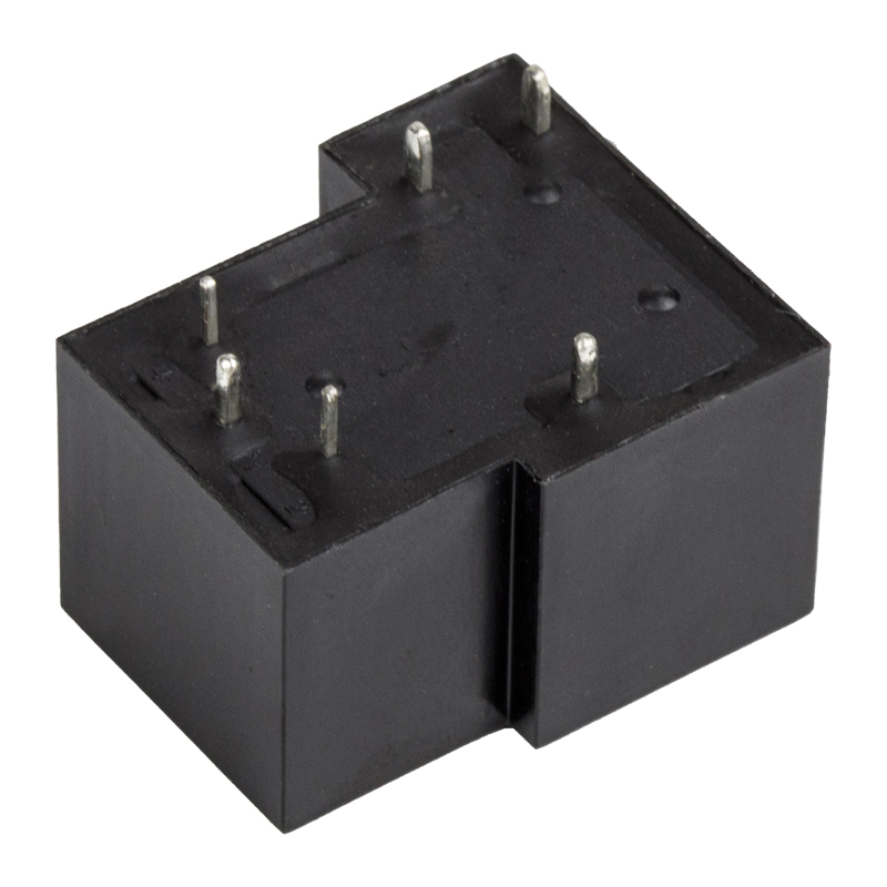 HLS-T90 SPDT 30A High Power PCB Relay with 5/6 Pin OptionsThis heavy-duty relay suits auxiliary loads like heaters or contactor coils outside the safety loop, offering high current switching and long mechanical life for continuous machine cycles.View Product →
Another difference appears in life expectancy. Emergency stop relays are expected to operate rarely, often only a few times per shift, and their contacts are sized for the inductive load of contactor coils. Standard power relays may be rated for hundreds of thousands of operations at their nominal load, which suits continuous machine cycles. Exchanging one for the other shortens the life of the component and creates a hidden weakness in the panel.
From a procurement standpoint, a panel builder can standardize on one or two emergency stop relay models and one family of standard power relays. This reduces spare-parts inventory and training costs. When ordering from a relay supplier, it is reasonable to ask for both product lines from one source so that the documentation, certificates, and terminal layouts follow a consistent pattern.
Key conclusion: use an emergency stop relay inside the safety function and a standard power relay outside it; never substitute one for the other.
Application Scenarios and Selection Points
Every machine has its own combination of hazard sources, operating cycles, and access methods, and that combination determines how the emergency stop relay should be configured. Below are the most common scenarios and the selection points that matter in each.
Machine tools and metalworking
Lathes, milling machines, and grinding machines have a main spindle, axis drives, and coolant pumps. The emergency stop relay must disconnect the spindle contactors and send a stop signal to the CNC. Because operators frequently open doors to change tools, a relay with dual-channel door monitoring is often used. The key selection point is the number of output contacts, which must be enough to cover the spindle, the axis-drive enable signal, and the hydraulic unit.
Packaging and converting equipment
Wrapping machines, filling lines, and cartoners run at high speed and experience frequent jams. The e-stop relay must respond quickly, and the reset procedure must be deliberate to prevent the machine from restarting while an operator's hand is inside the guard. A monitored reset input is strongly recommended. Sealed housings are preferred for machines that are cleaned with water or chemicals.
Robotic cells and material handling
Robotic cells combine multiple hazard sources: the robot arm, the turntable, the welding supply, and the conveyor. The safety architecture normally uses dual-channel e-stop buttons at several locations, all wired into the same safety relay or a small safety controller. Selection focuses on the number of series-connected stop buttons and the ability to distinguish between a short circuit and a genuine stop command.
Presses, shears, and forming machinery
Mechanical and hydraulic presses require the highest safety integrity level. The emergency stop relay is often part of a more complex circuit that includes two-hand controls and light curtains. The relay must have a certified PL e rating and must monitor the contactor stack through a feedback loop. A time-delay version may be needed to allow a controlled ram stop at the end of the stroke.
Food, beverage, and pharmaceutical lines
Sanitary environments impose washdown requirements, so the relay should be installed in a cabinet with appropriate ingress protection. Contact rating and terminal style are the selection priorities because the machine's control circuit may use 24 V DC PLC outputs rather than direct AC contactor coils.
Elevators, amusement rides, and special applications
In public-facing equipment, the emergency stop function is usually combined with a reset key and remote status indication. The relay needs auxiliary normally closed contacts for the remote monitoring system and a keyed reset switch. Certification requirements may go beyond ISO 13849 to local elevator or ride-safety standards.
For automation panels that need many auxiliary control circuits in addition to the safety loop, a transparent 10 A relay with four changeover contacts is a practical building block for PLC output buffering, status LED circuits, and interlock logic. Combining it with a matching socket simplifies wire routing and maintenance.
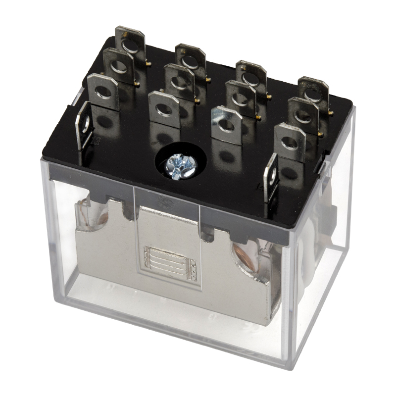 HLS-13F-4 Transparent 14-Pin 4PDT 10A PCB Relay with Quick PinWith four changeover contacts and a 10 A rating, this relay is ideal for PLC output buffering, indicator circuits, and interlock logic in automation panels, compatible with matching sockets.View Product →
In every scenario, the selection points come back to the same five questions. How many input channels are required? How many output contacts must open when the e-stop is activated? What reset mode matches the machine procedure? What is the supply voltage and terminal style? And what ambient conditions will the relay see inside the cabinet?
Key conclusion: application-specific selection is about translating machine hazards into channel counts, contact counts, and reset behavior, not about choosing the largest relay available.
Wiring, Installation, and Practical Compliance
Correct wiring has a greater impact on the reliability of an emergency stop relay than almost any other factor. A certified safety relay can be made unsafe by a single reversed wire or a missing feedback connection. The following practices cover the most important wiring and installation points.
Dual-channel wiring
For a dual-channel input, both channels must be wired so that a short circuit between them can be detected. The emergency stop button's two normally closed contacts are connected in series between the input terminals and the common return. Many relays require a cross-fault check: if the two channels change state at different times, the relay treats the event as a fault and locks out.
Feedback monitoring of contactors
When the emergency stop relay switches a set of contactors, the normally closed auxiliary contacts of those contactors should be wired into the feedback input of the relay. This verifies that the contactors actually opened. If one contactor welds, the feedback loop breaks, and the relay prevents the next start. This is a basic requirement for Category 3 and Category 4 architectures.
Reset wiring
The reset button should be wired with a rising edge into the reset input. A monitored reset requires the button to be released before the relay re-enables; a stuck reset button is detected and treated as a fault. Do not bridge the reset input unless your risk assessment explicitly allows automatic reset.
Earthing and EMC
The relay's protective earth terminal must be connected to the cabinet earth bar. Signal cables to the e-stop button should be separated from power cables. Shielded cable is recommended for long runs or in environments with frequency inverters and welding equipment.
Practical compliance checklist
| Design phase | Before commissioning |
|---|---|
|
|
Using plug-in sockets for auxiliary relays simplifies these checks. When a relay in the control circuit fails, the technician can unplug it and insert a spare in a matter of seconds without touching the wiring. This speeds up commissioning and reduces the risk of wiring mistakes during repairs.
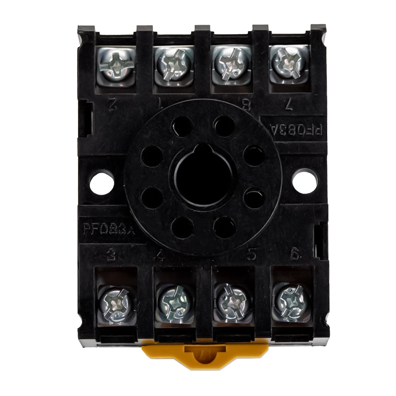 HLS-PF083A Relay Socket for MK2P Plug-In InstallationThis socket enables fast relay replacement without rewiring, simplifying maintenance in control cabinets and helping technicians trace safety circuits through neat, accessible terminal connections.View Product →
At the cabinet level, terminals should be labeled with the wire numbers from the schematic. The emergency stop circuits should be visually identifiable, for example by a separate terminal strip or a physical separation distance from power wiring. This allows an external auditor or a new technician to trace the safety circuit quickly.
Key conclusion: wire the emergency stop relay according to its channel and feedback requirements, test the latched behavior after every change, and use plug-in sockets for fast maintenance.
Maintenance and Troubleshooting
Emergency stop relays are designed to be fail-safe, but they still require periodic inspection and testing. The testing frequency depends on the risk level of the machine and the requirements of the applicable standard. A common recommendation is to test the emergency stop function at least once per shift by pressing the button and verifying that the machine shuts down, and to perform a deeper inspection of the relay and its wiring annually or during scheduled maintenance.
Regular inspection should include the following steps: check that the emergency stop button is not mechanically damaged, confirm that the relay's status indicators show the expected state, measure the supply voltage, verify that the input channels are free of short circuits, and test that the reset procedure works only when the button is released.
Common faults and corrective actions
| Symptom | Likely cause | Corrective action |
|---|---|---|
| Relay does not switch to ready state | Input channel open, missing voltage, or faulty reset | Check button contacts, wiring, and reset button |
| Relay trips immediately after reset | Welded contactor in the feedback loop | Replace the welded contactor and re-test |
| One channel always detected as faulty | Cross-wiring or short circuit between channels | Trace the two channels and repair the wiring |
| Relay latches but outputs stay closed | Internal fault or welded output contact | Replace the relay and check the load circuit |
| Spurious trips during machine operation | EMC interference or loose terminals | Improve earthing, separate cables, retighten terminals |
| Reset button has no effect | Stuck button, wrong edge detection, or latching fault | Replace button and verify the reset input logic |
When a fault appears on an emergency stop relay, the correct reaction is not to bypass the relay or bridge its input contacts. Doing so destroys the safety function and exposes workers to unacceptable risk. Instead, technicians should isolate the machine, follow the manufacturer's diagnostic procedure, and replace the faulty component.
The relay itself has a limited service life. Contact wear, coil aging, and contamination of the mechanical linkage eventually affect the force-guided mechanism. Many manufacturers specify an expected relay life in number of operations or years of service. For aged machines, replacing the emergency stop relay as part of a major overhaul is a low-cost way to restore the original safety performance.
Spare part management should include at least one emergency stop relay of each model installed in the plant. Because the relays are identical across multiple machines, a single spare can cover a whole production line. Keeping the spare in a labeled location, together with the corresponding socket and a copy of the wiring diagram, reduces downtime significantly.
For plants that buy through a relay manufacturer or wholesaler, we recommend requesting the official certification documents at the time of purchase. The certificates should be kept with the machine documentation so that an auditor can verify the PL/SIL rating without contacting the supplier afterwards.
Key conclusion: test emergency stop relays regularly, replace rather than bypass a suspect relay, and keep certified spare parts with the wiring documentation.
Emergency Stop Relay FAQ
Short answers to the most frequent questions we receive about emergency stop relays.
What is an emergency stop relay?An emergency stop relay is a safety-rated control device that supervises an emergency stop button and disconnects the machine's enabling circuits through force-guided contacts. It provides redundant input channels, internal fault detection, and a deliberate reset function so that a welded contact or wiring fault does not leave the machine energized. |
Can I use a standard relay for an emergency stop circuit?No. A standard power relay has no force-guided contacts, no channel monitoring, and no declared response time. It does not meet the failure behavior required by ISO 13849 or IEC 62061. It may be used in auxiliary circuits outside the safety function, but not as the emergency stop relay. |
What does dual-channel wiring mean?Dual-channel wiring uses two separate input paths from the emergency stop button to the relay. Each channel is monitored independently, and the relay checks that both channels change state together. If one channel is shorted or broken, the relay detects the fault and prevents the machine from starting. |
What is the difference between automatic and manual reset?Automatic reset re-closes the enabling contacts as soon as the e-stop button is released and the inputs are closed. Manual reset requires the operator to press a separate reset button after the inputs are closed. Monitored reset also verifies that the reset button itself works correctly. Most standards require manual or monitored reset to prevent unexpected restart. |
What performance level do I need?Performance level is determined by a risk assessment. A simple machine with a low frequency of access and minor consequences may need PL d, while a press or a robot cell often requires PL e with Category 3 or 4 architecture. Review the risk assessment before selecting the relay and confirm the declared rating in the certificate. |
How often should I test the emergency stop function?The stop function should be tested at the beginning of each shift or as defined in the machine's operating manual. A deeper inspection of the relay, wiring, and feedback loop should be part of the periodic maintenance schedule. The relay's response time and contact behavior are verified by the manufacturer design, but the overall function depends on the wiring and the contactors. |
Key conclusion: use a certified safety relay, understand its channel and reset logic, and test the complete safety function regularly.
Related Resources and Support
For engineers and buyers who want to deepen their knowledge of relay selection and control circuits, the following resources are available on our site.
Related resources:
Next step: define your channel count, output contacts, and reset mode, then contact the supplier with a complete specification.


