



 English
 中文简体
中文简体Content
- 1 What Is an Overcurrent Relay?
- 2 How Does an Overcurrent Relay Work?
- 3 Types of Overcurrent Relays
- 4 Overcurrent Relay Settings and Coordination
- 5 Application Scenarios of Overcurrent Relays
- 6 Selecting Relays for Protection and Control Circuits
- 7 Quality and Reliability Considerations for Protection Circuits
- 8 Mounting, Wiring, and Maintenance of Relays in Protection Panels
- 9 Common Relay Problems and Troubleshooting
- 10 Frequently Asked Questions About Overcurrent Relays
- 10.1 What is the difference between ANSI 50 and 51 overcurrent relays?
- 10.2 Can overcurrent relays operate without a circuit breaker?
- 10.3 Why do inverse time relays have different curve families?
- 10.4 Are overcurrent relays suitable for motor protection?
- 10.5 How often should overcurrent relays be tested?
- 10.6 Can a standard power relay replace an overcurrent relay?
- 11 Final Thoughts and Where to Start
A maintenance engineer in a small bottling plant watched the same feeder trip three times in one week, every trip occurring at roughly 130 percent of the motor full-load current. A few kilometers away, a factory lost an entire production line because a short circuit took two full seconds to clear, long enough for switchgear to be damaged beyond repair. Both situations share one root cause: the overcurrent protection was not matched to the equipment it protected. Overcurrent relays are the first line of defense in almost every low- and medium-voltage protection scheme, and choosing the right relay, setting it correctly, and pairing it with a dependable switching element decides whether an abnormal current becomes a controlled stop or a catastrophic failure.
This article explains overcurrent relays from a practical standpoint: what they are, how they operate, which types exist, how coordination and settings work, where they are applied, and what a buyer should check when sourcing relays from a relay manufacturer, supplier, or wholesaler. Because protection is only as strong as the components inside the panel, the discussion also covers the power relays and sockets that carry the trip signal to the circuit breaker, with selection guidance based on real production and field experience.
Key conclusion: the reliability of any overcurrent protection scheme depends less on a single smart device than on the correct combination of measuring relay, trip relay, wiring, and maintenance.
What Is an Overcurrent Relay?
An overcurrent relay is a protective device that continuously compares the current flowing in a circuit with a preset pickup value. When the current exceeds that value and remains above it for the required time, the relay closes its output contact and sends a trip command to the circuit breaker. In ANSI device-number terminology, instantaneous overcurrent protection is designated 50 and time-delay overcurrent protection is designated 51, which is why industrial drawings commonly refer to 50/51 relays in the same protection function.
The current signal is normally brought to the relay through a current transformer that steps the primary current down to a secondary level, usually 1 A or 5 A. The relay compares this scaled current against the pickup setting, evaluates whether a fault condition exists, and then acts according to its time-current characteristic. The final switching of the breaker trip coil is almost always performed by a separate power relay or contactor because the measuring contacts of a protection relay are not designed to interrupt large inductive DC loads.
This distinction matters for buyers. An overcurrent relay measures and decides; a power relay switches. Both are needed in a typical protection circuit, and panel builders frequently source them from the same relay manufacturer to guarantee compatibility of coil voltage, contact rating, and mounting layout. If you are replacing an existing protection scheme, you should verify not only the protection relay settings but also the ratings of the auxiliary relays that execute the trip.
Key conclusion: an overcurrent relay is a decision-making element, and it needs a properly rated output relay and circuit breaker to complete the protection chain.
How Does an Overcurrent Relay Work?
The operating sequence of an overcurrent relay can be broken down into four stages: current detection, fault evaluation, time delay, and tripping. In the detection stage, the current transformer feeds a scaled copy of the line current into the relay coil or electronic input. The relay compares this value against the pickup current setting. If the measured current stays below pickup, the relay remains in its normal state and takes no action.
When the current rises above pickup, the relay enters the timing stage. For an instantaneous element, the trip signal is issued within a few milliseconds with no intentional delay. For a time-delay element, the relay runs an internal timing calculation based on its selected characteristic. The most common mathematical model for inverse time relays is t = K / ((I / Ip)^α − 1), where I is the fault current, Ip is the pickup current, and K and α define the curve shape. By changing K, engineers adjust the time multiplier setting; by changing α, they select a normal inverse, very inverse, or extremely inverse curve.
Once the calculated time elapses, the relay closes its output contact, energizing the trip circuit. In an electromechanical design, a magnetic armature moves against a spring and closes a contact; in a numerical design, a microprocessor performs the same logic and drives a solid-state output or a sealed relay output. The trip signal then passes through the breaker trip coil, either directly or through an auxiliary power relay that provides contact amplification and isolation.
After the breaker opens and the fault current disappears, the relay resets. The dropout ratio, usually expressed as a percentage of pickup, determines how far the current must fall before the relay returns to normal. A typical dropout ratio lies between 0.85 and 0.97, which prevents contact chatter near the pickup threshold and gives a stable reset after the fault is cleared.
Key conclusion: the practical meaning of a relay curve is simple: higher fault current means faster tripping, and the pickup value decides where the protection starts to act.
Types of Overcurrent Relays
Overcurrent relays are grouped by their time-current behavior. The four families described below cover the vast majority of industrial installations, and understanding them is the first step in any relay selection exercise.
Instantaneous Overcurrent Relays
An instantaneous relay operates as soon as the current exceeds its pickup level, with no intentional delay. It is used for fast fault clearing on feeders and as a high-set element in a two-stage protection scheme. Because it cannot discriminate between a serious fault and a temporary inrush transient, it must be set well above the maximum legitimate current seen by the circuit.
Definite Time Overcurrent Relays
A definite time relay picks up when current exceeds the setting, then waits a fixed, user-adjustable delay before tripping. The delay does not change with the magnitude of the fault. This makes coordination simple, but it also means a heavy fault does not receive faster clearance than a moderate overload.
Inverse Time Overcurrent Relays
Inverse time relays, often called IDMT relays, operate faster as the current increases. This behavior matches the thermal damage curve of cables, transformers, and motors, so the relay clears serious faults quickly while tolerating short overloads. Curve families include normal inverse, very inverse, extremely inverse, and long-time inverse, each suited to different equipment.
Directional Overcurrent Relays
Directional overcurrent relays measure both current magnitude and phase angle, operating only when the current flows in a defined direction. They are essential in meshed networks, parallel feeders, and generator protection, where fault current can circulate in both directions.
| Relay type | Operating response | Typical application | Main strength / limitation |
|---|---|---|---|
| Instantaneous | Trips within milliseconds above pickup | High-set element, fault clearing near source | Very fast, but no discrimination against transients |
| Definite time | Fixed delay after pickup | Feeder backup, bus protection coordination | Easy to coordinate, but slow for heavy faults |
| Inverse time (IDMT) | Faster trip as current increases | Motor, transformer, and cable protection | Matches thermal curves, but curve study is required |
| Directional | Trips only for current in a set direction | Mesh networks, parallel feeders, generators | Prevents incorrect trips, but requires VT polarity |
Time-current curves are the clearest way to compare relay behavior. The horizontal axis shows current expressed as a multiple of the pickup setting. The vertical axis shows operating time on a logarithmic scale. Each curve indicates when a relay will issue a trip command for a given current level. The chart below compares a typical instantaneous, definite time, and inverse time characteristic.0.5
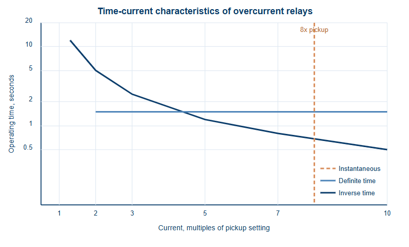
The inverse time curve in the chart starts at about 1.3 times pickup and drops from roughly 12 seconds toward 0.5 seconds as the current increases. This means a moderate overload is cleared within a few seconds while a solid short circuit is cleared almost immediately. The definite time line remains flat at 1.5 seconds for every current above 2 times pickup, so the protection interval is predictable regardless of fault severity. The dashed instantaneous line operates without intentional delay at 8 times pickup, which makes it ideal for clearing very high fault currents before they stress equipment. Reading the three characteristics together shows why most protection engineers use inverse time as the base element and add a definite time or instantaneous stage for speed. The inverse curve provides good discrimination with downstream fuses and other relays because lower fault currents at the far end of a feeder naturally produce longer operating times. The definite time element offers a simple way to add backup protection when coordination margins are difficult to achieve with inverse curves alone. The instantaneous element acts as a final fast stage that does not wait for the time dial and catches the highest fault currents within the zone. When relays are set in series, the upstream relay must be slower than the downstream relay by a coordination margin, usually 0.3 to 0.5 seconds. The shape of the curve directly determines whether that margin is respected across the whole range of possible fault currents. A curve that is too sensitive will create nuisance trips, while a curve that is too flat will cause unnecessary delays for serious faults. This is why curve selection is a genuine engineering decision and not simply a catalogue pick.
Key conclusion: matching the relay curve to the protected equipment is the single most important setting decision, because it balances operating speed against discrimination.
Overcurrent Relay Settings and Coordination
Setting an overcurrent relay involves two numbers: the pickup current and the time delay. Pickup should be high enough to ride through normal load variations and motor starting currents, but low enough to detect every fault condition in the protected zone. A common rule is to set phase overcurrent pickup at 1.05 to 1.25 times the maximum expected load current, and to verify that the minimum fault current is at least 1.5 times the pickup to ensure reliable operation.
Time coordination, or discrimination, ensures that the protection device closest to the fault operates first. The upstream relay must wait for the downstream relay and the breaker to clear the fault before it starts its own timing. The coordination interval accounts for breaker opening time, relay overshoot, and a safety margin. In electromechanical schemes, an interval of 0.3 to 0.5 seconds is common; in numerical schemes, careful grading can reduce it to 0.2 seconds or less.
- Draw the one-line diagram and identify the zone of protection for each relay.
- Calculate the minimum and maximum fault current at each relay location.
- Select the relay characteristic that matches the protected equipment.
- Set the pickup current for the highest continuous load plus a safety margin.
- Calculate the time dial or time multiplier so that each relay clears its zone within the coordination interval.
- Plot the time-current curves of all relays on the same chart and verify the margins.
- Test the settings by secondary injection and record the results.
| Protection element | Pickup setting | Time setting | Purpose |
|---|---|---|---|
| Phase overcurrent, inverse time | 1.15 x full-load current | Normal inverse curve, TMS 0.15 | Overload protection and feeder backup |
| Earth fault, inverse time | 0.2 x full-load current | Very inverse curve, TMS 0.10 | Ground fault detection with low sensitivity |
| Instantaneous high set | 8 x full-load current | No delay | Fast clearing of solid faults in the motor leads |
Coordination becomes more complex when motors, transformers, and capacitor banks are involved, because each has its own inrush characteristics. Motors draw starting currents of 6 to 8 times full load for several seconds, so a motor protection relay must allow the motor to start without tripping. Transformers produce magnetizing inrush that can reach 8 to 12 times rated current for a few cycles, requiring a time delay or harmonic restraint. These application constraints are why the same physical relay may hold completely different pickup and time dial settings from one installation to the next.
Key conclusion: a relay setting is only correct if it has been coordinated with every other protection device in the circuit, not if it works in isolation.
Application Scenarios of Overcurrent Relays
Overcurrent relays appear in almost every part of an electrical network, but the selection priorities differ by application. On distribution feeders, the main concerns are discrimination with downstream fuses and fast clearing of phase and earth faults. On transformers, the overcurrent relay is usually a backup to differential protection and must withstand magnetizing inrush while responding to winding and bushing faults.
For motor circuits, thermal protection and starting current are the dominant constraints. The relay must ride through the starting period, protect the motor against sustained overload, and trip quickly on locked-rotor or short-circuit conditions. On generators, overcurrent protection must coordinate with the excitation system and avoid operating during stable power swings, so directional and voltage-controlled characteristics are often used instead of a plain inverse curve.
| Protected equipment | Common relay type | Main setting consideration |
|---|---|---|
| Distribution feeder | Inverse time plus instantaneous | Discrimination with downstream protection devices |
| Transformer | Inverse time with inrush restraint | Ride through magnetizing inrush, clear winding faults |
| Motor | Inverse time, long-time inverse curve | Allow normal starting, protect against locked rotor |
| Generator | Voltage-controlled or directional | Avoid operation during power swings and external faults |
| Capacitor bank | Definite time plus unbalance protection | Handle switching transients, detect failed elements |
In every scenario, the trip signal produced by the overcurrent relay must reach the breaker reliably. This is where the mechanical part of the protection chain becomes critical: auxiliary relays, terminal blocks, sockets, and wiring must all be rated for the duty they perform. A protection relay with a perfect characteristic curve is useless if its trip path fails at the moment of a fault.
Key conclusion: application context decides the relay characteristic, but the trip path components decide whether the protection actually operates when it is needed.
Selecting Relays for Protection and Control Circuits
When panel builders and maintenance teams order relays for protection circuits, they usually need two categories of components. The first is the protection relay itself, which performs the measurement and logic. The second is the output or auxiliary relay that switches the breaker trip coil, control signals, and status indication circuits. Buyers who search for an overcurrent relay manufacturer, supplier, or wholesaler are often looking for both categories in one order, which simplifies stock control and guarantees that coil voltages and terminal arrangements match.
For the trip circuit, contact rating is the first thing to verify. A breaker trip coil can draw anywhere from 2 A to 10 A at DC, and the circuit is strongly inductive. A relay contact rated for 5 A at 250 VAC may fail after a few operations if it is used to switch a DC trip coil without an appropriate contact rating. The practical choice is a power relay with generous contact margins, such as a component with a 16 A or 30 A contact rating and a coil voltage that matches the panel supply.
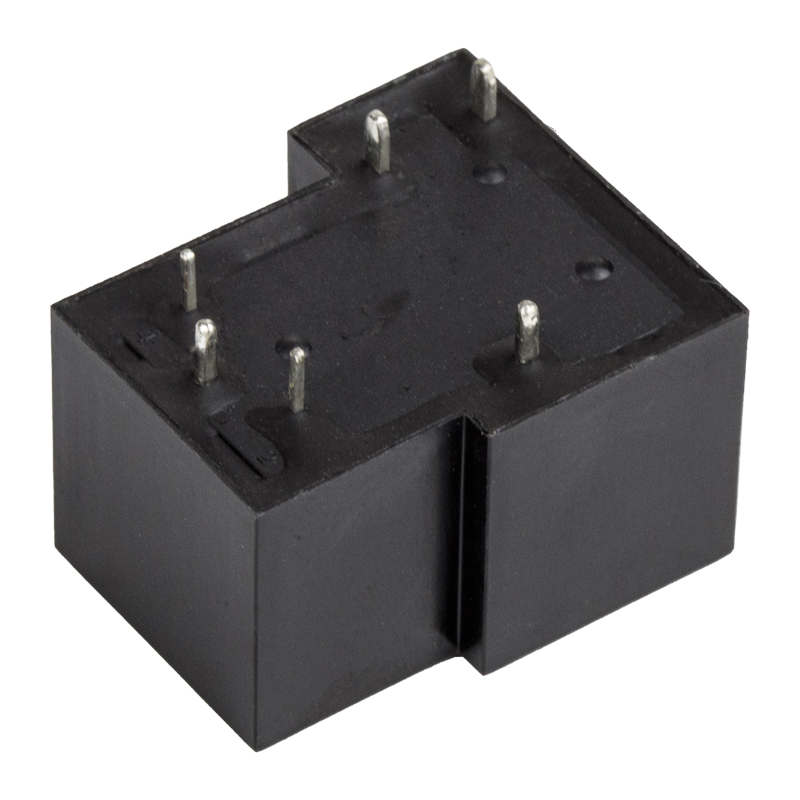 T90 Series 30A SPDT Power Relay with PCB Pin TerminalsThis high-current relay suits trip and interface circuits where inductive DC loads demand generous contact margins. Its 30 A rating and PCB pin configuration make it a practical choice for industrial panel builders.View Product →
One practical example is the T90 series power relay with SPDT contacts and a 30 A rating, which is frequently used as a trip relay, interface relay, or contactor driver in industrial panels. When selecting such a component, the engineer must also confirm the pin assignment, the allowable coil voltage range, and whether PCB pin or quick-connect terminals fit the panel layout.
Breaker trip coil switching
|
Control panel interface
|
Mounting is the second major decision. Protection panels often mix PCB-mounted relays, quick-connect terminal relays, and plug-in socket relays depending on how often replacement is expected. The three options cover different maintenance philosophies, and the choice is usually made during panel design.
PCB pin mounting
Relay is soldered directly to the control board. Lowest cost, compact, but replacement requires desoldering.
Quick-connect terminals
Fast-on tabs accept insulated female connectors. Good for wiring harnesses in automotive and appliance panels.
Plug-in socket mounting
Relay plugs into a socket with screw terminals. Fastest replacement in the field and easiest to inspect.
Procurement checklists for protection-related relays should also cover certifications. UL, TUV, CE, CQC, and RoHS compliance tell the buyer that the component has been tested for the target market, and ISO9001 certification at the factory indicates that production processes are controlled. OEM and ODM cooperation is common in this industry, and an experienced relay manufacturer will confirm whether a specific pinout and mounting layout are compatible with an existing design before a single sample is shipped. These details might look like paperwork, but they are exactly what protects a panel builder from field failures and compliance problems later.
Key conclusion: the correct protection relay deserves a correctly rated trip relay, and both should meet the certifications, mounting style, and endurance required by the target market.
Quality and Reliability Considerations for Protection Circuits
Protection equipment operates rarely, but when it does operate, failure is not acceptable. This puts a special burden on relay quality. A relay that welds its contacts or fails to close on command turns a minor fault into a major outage, so buyers should evaluate the same parameters that a factory uses in its own testing: contact material, mechanical endurance, electrical endurance, and environmental limits.
Contact material affects both the switching capacity and the contact resistance over time. Silver alloy contacts are standard for power relays, and the specific alloy influences resistance to welding and arc erosion. Mechanical endurance is expressed as the number of operations without load; electrical endurance is measured under a defined load, because every arc slightly erodes the contacts. Class F or Class B coil insulation is common, and the operating temperature range should cover the environment inside the panel, typically minus 40 to plus 70 degrees Celsius.
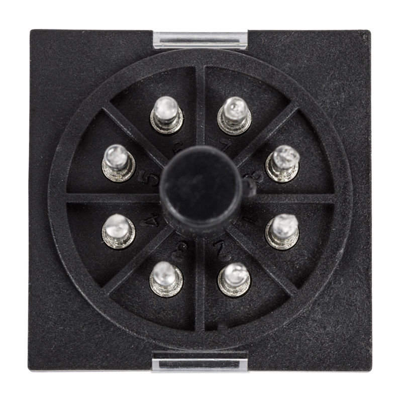 MK2P Transparent 8-Pin 10A Changeover Power RelayWith two changeover contacts and a clear housing, this plug-in relay allows quick visual inspection and simple replacement in protection and automation panels. Its silver alloy contacts support reliable switching under load.View Product →
A good example of a dependable control relay is the MK2P transparent 8-pin relay with two changeover contacts, widely used in industrial protection and automation panels. The transparent housing allows a quick visual check of contact state, and the plug-in base makes replacement simple. When a relay like this is used as an interface between protection logic and power circuits, its quality directly affects the availability of the whole protection system.
| Quality item | Why it matters | Typical requirement |
|---|---|---|
| Contact material | Resistance to welding and arc erosion under fault switching | Silver alloy, matching load type |
| Mechanical endurance | Long service life in control duty | 10 million operations or more |
| Electrical endurance | Ability to interrupt rated load repeatedly | 100,000 operations at rated load |
| Coil insulation class | Resistance to heat and voltage stress | Class F or Class B |
| Approvals | Market acceptance and safety compliance | UL, TUV, CE, CQC, RoHS |
Buyers should also ask how the factory verifies these parameters. A stable relay manufacturer maintains test records for contact resistance, pickup and dropout voltage, dielectric strength, and endurance. When a batch of relays is destined for protection panels, lot traceability becomes valuable, because a faulty component can then be traced back to its production batch and corrected quickly.
Key conclusion: choose relays for protection circuits on the basis of documented endurance, approvals, and process control, not only on price.
Mounting, Wiring, and Maintenance of Relays in Protection Panels
How a relay is mounted and wired has as much influence on reliability as the relay itself. Screw terminals should be tightened to the recommended torque, because a loose connection creates heating and intermittent operation. Coil suppression is mandatory in DC circuits: a flyback diode or RC snubber across the coil absorbs the inductive energy and prevents voltage spikes that can damage protection electronics. Contact loads should be kept within the relay rating with a margin, because inductive loads such as contactor coils and solenoid valves produce arcing that shortens contact life.
Plug-in relays offer the simplest maintenance path. When a socket-mounted relay fails or needs testing, it can be pulled out and replaced in seconds without disturbing the panel wiring. This philosophy is deeply embedded in industrial panel design, which is why socket relays such as the MK2P family remain common decades after their introduction.
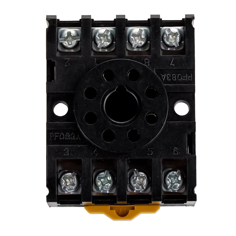 PF083A Relay Socket Compatible with MK2P SeriesThis socket provides secure pin clamping and clear terminal markings for MK2P relays, enabling fast maintenance without rewiring. It carries the same current as the relay, so its rating and footprint are critical for replacements.View Product →
Relay sockets are not passive accessories; they carry the same current and must be rated for the circuit. A good socket provides reliable clamp force on the relay pins, clearly marked terminal numbers, and adequate creepage distance between circuits. When replacing an imported relay with a local equivalent, the buyer must confirm that the pin arrangement and socket footprint match, because even a small difference in pin spacing can make the replacement impossible.
- Monthly visual inspection: check for discoloration, dust, loose wiring, and signs of arcing.
- Quarterly re-torque of screw terminals and inspection of socket pin grip.
- Semi-annual operation test: energize the relay and verify contact continuity and timing.
- Annual secondary injection test of the complete protection chain, from current transformer to breaker trip.
- After any fault event, inspect and replace relays that operated at or near their rated limits.
Storing spare relays correctly also extends their life. Relays should be kept in their original packaging, in a dry clean room, away from dust, humidity, and corrosive gases. If relays are stored for years before installation, a sample test before commissioning is a sensible precaution.
Key conclusion: the fastest way to keep protection circuits available is to use socket-mounted relays, keep clean spare stock, and follow a simple periodic test routine.
Common Relay Problems and Troubleshooting
Field failures in relay circuits usually fall into a few recognizable patterns. The relay trips when it should not, the relay fails to trip when it should, or the relay itself is damaged. Each pattern points to a different set of causes, and the cure starts with careful observation rather than immediate replacement.
| Symptom | Likely cause | Corrective action |
|---|---|---|
| Nuisance tripping during motor start | Pickup too low or curve too sensitive for starting current | Raise pickup, use a longer inverse curve, check for harmonics |
| Relay trips but breaker does not open | Trip relay contact failed, wiring open, or breaker mechanism faulty | Test the trip path component by component, starting at the relay output |
| No trip on a real fault | Wrong setting, CT wiring open, relay stuck, or coil failure | Verify CT secondary continuity, settings, and relay operation |
| Burnt relay coil | Wrong coil voltage, undervoltage, or continuous over-excitation | Measure actual coil voltage, replace with correct coil rating |
| Chattering contact | Low coil voltage, poor contact, or mechanical vibration | Stabilize supply, clean or replace contacts, improve mounting |
Many of these symptoms can be avoided before they appear. A panel designer who checks contact ratings, uses coil suppression, and selects relays with adequate mechanical endurance will see far fewer field failures. On the maintenance side, the most valuable habit is to document every relay setting and every test result, because a protection circuit that has no recorded baseline is very hard to troubleshoot under time pressure.
Key conclusion: most relay circuit failures are caused by settings, wiring, or wrong component ratings rather than by a defective relay, so troubleshooting starts with the circuit, not the spare parts bin.
Frequently Asked Questions About Overcurrent Relays
What is the difference between ANSI 50 and 51 overcurrent relays?ANSI 50 refers to instantaneous overcurrent protection, which operates immediately when current exceeds the pickup value. ANSI 51 refers to time-delay overcurrent protection, which operates after a time interval that depends on the selected curve. In practice, a single protection function often combines both: a 51 element for overload and backup protection, and a 50 element for fast clearing of high fault currents. |
Can overcurrent relays operate without a circuit breaker?An overcurrent relay only produces a trip signal; it cannot interrupt fault current by itself. A circuit breaker or contactor must be available to physically open the circuit. In some low-current applications, a relay can directly switch the load, but for protection purposes the relay should always be considered the brain and the breaker the muscle that executes the command. |
Why do inverse time relays have different curve families?Different equipment has different thermal and mechanical tolerances. A normal inverse curve is a good match for cables and distribution feeders, a very inverse curve suits transformers and some motor applications, and an extremely inverse curve provides faster clearing for faults close to the source. Long-time inverse curves are used for motor thermal protection where starting currents must be tolerated. The curve family is chosen to match the protected equipment while maintaining coordination with neighboring devices. |
Are overcurrent relays suitable for motor protection?Yes, but the relay must ride through the motor starting current, which can be 6 to 8 times full-load current for several seconds. A long-time inverse curve with an appropriate pickup setting and a stall protection element is a proven approach. Many motor protection schemes use a combination of inverse time overcurrent for overloads, an instantaneous element for short circuits, and an earth fault element for ground faults. |
How often should overcurrent relays be tested?Most standards recommend a full secondary injection test every one to two years for critical protection relays. Panel-based checks, such as confirming pickup and timing, should be done more frequently, especially after a fault event or a setting change. The test frequency also depends on the application: generator and transformer protections are usually tested more often than non-critical feeder protection. |
Can a standard power relay replace an overcurrent relay?No. A standard power relay is a switching device; it does not measure current, compare it with a pickup setting, or calculate an inverse time delay. These functions require a protection relay. However, power relays are essential partners in protection circuits as trip relays, interface relays, and contact amplifiers. When sourcing from a relay manufacturer, supplier, or wholesaler, you should select a protection relay for the measuring role and a suitably rated power relay for the output role. |
Key conclusion: the overcurrent relay makes the decision, the breaker executes it, and the auxiliary relay in between must be chosen and maintained with the same care as both.
Final Thoughts and Where to Start
Overcurrent relays have protected electrical systems for more than a century, and the fundamentals have not changed: detect the abnormal current, judge its severity, and open the circuit in a controlled way. Modern numerical relays add communication, fault recording, and adaptive settings, but they still rely on the same pickup, timing, and coordination logic that engineers have used for decades. This is good news for buyers, because it means a solid understanding of relay characteristics will never become outdated.
When you prepare a specification for protection components, start with the relay types and settings, then add the output relays, sockets, and accessories that complete the trip path. Confirm certifications, endurance ratings, and mounting compatibility with the existing panel. If you are replacing an imported relay, verify that the terminal layout and pinout match the socket before you place the order. A small difference in the drawing can turn a simple replacement into a redesign.
Two articles from our engineering library cover relay selection and field failures in more detail:
- Precautions for relay selection — a practical checklist of ratings, mounting, and environmental factors that should be reviewed before buying.
- Common relay problems and handling measures — field symptoms and the corrective actions that resolve them.
If you are evaluating relays for a protection panel, an upgrade, or an OEM project, it helps to work with a supplier that understands both the protection side and the switching side of the circuit. The engineering team behind this article builds relays and relay sockets for industrial, automotive, and automation applications, and the production line is open for custom requirements, including OEM and ODM cooperation.
Key conclusion: a successful overcurrent protection project is the sum of the right relay characteristic, the right output relay, the right socket, and the right maintenance habit, and each of these is a choice you can control.


