



 English
 中文简体
中文简体Content
- 1 What Is a Phase Loss Relay?
- 2 Why Phase Loss Protection Is Critical for Three-Phase Motors
- 3 How Does a Phase Loss Relay Work?
- 4 Main Types of Phase Loss Relay and Their Differences
- 5 Key Specifications and Phase Loss Relay Selection Criteria
- 6 Phase Loss Relay Applications Across Industries
- 7 Phase Loss Relay Wiring and Installation Guide
- 8 How to Test and Maintain a Phase Loss Relay
- 9 Buying Phase Loss Relay Components from a Relay Manufacturer
- 10 Phase Loss Relay FAQ
- 10.1 What is the difference between a phase loss relay and an overload relay?
- 10.2 Can a phase loss relay detect undervoltage and phase sequence errors?
- 10.3 How fast does a phase loss relay trip?
- 10.4 Do I need one phase loss relay for each motor?
- 10.5 How do I test a phase loss relay?
- 10.6 Can a phase loss relay protect a variable-frequency drive (VFD)?
A motor driving a packaging conveyor fails at 2 a.m. A fuse in the control circuit had blown an hour earlier, removing one phase from the supply. The motor did not stop; it kept humming, ran hot, drew excessive current in the remaining windings, and by the time the maintenance team arrived, the winding insulation was beyond repair. This is the classic single-phasing failure, and it is exactly the sequence of events that a phase loss relay is designed to interrupt.
A phase loss relay is a protective monitoring device that continuously supervises the three phases of a power supply, and drops out the control circuit when one phase is missing, the voltage falls below a set level, or the phase sequence is wrong. It reacts in fractions of a second, long before a thermal overload relay can respond to the slow heating that single-phasing produces.
This guide covers how a phase loss relay works, what types exist, which specifications matter when you buy one, how to install and test it, and why sourcing these relays from the right relay manufacturer matters for OEM builders and panel shops.
What Is a Phase Loss Relay?
A phase loss relay, also listed in catalogs as a phase failure relay, a phase loss protection relay, or a three-phase monitor relay, is installed between the three-phase supply and the motor starter. It measures whether all three phase voltages are present and roughly equal in magnitude. In more advanced models, it also checks the phase sequence. When a fault is detected, the relay switches its internal output contacts, and in doing so de-energizes the coil of an upstream contactor which then disconnects the motor.
Three points are worth understanding before you open a datasheet, because they guide everything else in this article.
- A phase loss relay detects supply-side faults. It does not replace an overload relay, which protects the motor from mechanical overload, locked rotor and prolonged starting. The two devices complement each other, and most protection schemes include both.
- A phase loss relay does not interrupt motor power directly. Its output contacts, typically one or two changeover contacts rated at 5 A or 10 A, control the coil of a contactor. Wiring a motor current through the relay contacts is a common installation mistake.
- Many phase loss relays also detect undervoltage and phase sequence errors. A reversed phase sequence can be as destructive as a lost phase, because a pump or compressor will rotate backwards and may be seriously damaged.
Seen from the user side, a phase loss relay is inexpensive insurance. For the cost of a standard control relay and a short wiring job, it removes the most frequent electrical cause of premature three-phase motor failure.
Why Phase Loss Protection Is Critical for Three-Phase Motors
When a three-phase motor loses one phase, it loses the rotating magnetic field that produces smooth torque. If the motor is stationary, it may hum and refuse to start. If it is already running, it continues on two phases with a serious drop in torque. Since the driven load does not normally reduce at the same rate, the motor slows down, the slip increases, and the current in the remaining stator windings climbs to 1.5 to 2 times the rated value.
An overload relay set at the motor rated current may take minutes to respond to this condition, because the single-phasing current can remain below its trip point for long enough to allow damaging temperatures to develop. The motor insulation system then begins to degrade quickly. As a rule of thumb, the expected life of a motor insulation system is reduced by half for every 10 °C increase in winding temperature. One hour of single-phasing can therefore cause damage comparable to weeks of normal operation.
The relationship between supply unbalance and motor temperature is not linear, and it explains why even a small phase problem deserves attention. The chart below shows the increase in motor temperature rise that is typically associated with different levels of voltage unbalance in a motor supply. The values follow the derating guidance that engineers use when a machine must operate on an unbalanced utility supply. A modest unbalance of 3% is enough to cause a measurable temperature problem. A complete phase loss is the extreme end of the same curve, where the temperature climb accelerates quickly towards insulation failure.
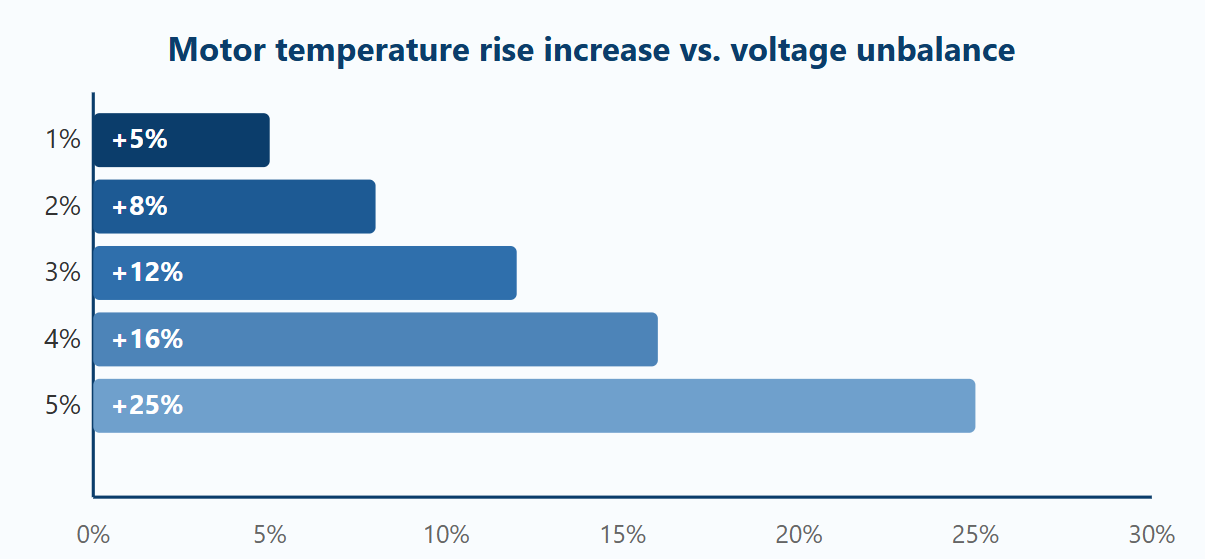
Reading from left to right, a perfectly balanced supply produces no additional temperature rise, so the starting point of the chart is zero. At 1% unbalance, the temperature rise increases by about 5%, which is barely noticeable in normal operation. At 2% unbalance, the extra temperature rise reaches roughly 8%, still acceptable in the short term but already reducing the thermal headroom of the motor. At 3% unbalance, the increase approaches 12%, which begins to shorten insulation life if the motor runs continuously. At 4% unbalance, typical engineering guidance recommends derating the motor, because the additional 16% temperature rise can push a fully loaded motor into an unsafe zone. At 5% unbalance, the temperature rise reaches about 25% above the balanced baseline, a level at which winding life is drastically reduced in a matter of weeks. At the far end of the same curve lies a complete single-phase condition, where the temperature climb can destroy insulation in minutes rather than weeks. This is why machine builders and plant engineers pay attention to unbalance values above 2%, and why protection relays are set to respond near the 3% level. In a real factory, a loose connection, a corroded contact, or a melted fuse can move the supply from perfectly balanced to dangerous unbalance in one moment. The protection logic must therefore react in seconds, not minutes, to make a difference. A correctly set phase loss relay trips before the motor temperature reaches the damaging zone that a delayed overload curve would allow. That is the practical difference between planning for a motor failure and actually preventing one.
| Without a phase loss relay | With a phase loss relay |
|---|---|
| The motor continues on two phases, current rises, windings overheat, and insulation degrades. Failure often occurs before the overload relay reacts. | The relay detects the missing phase within its response time, the contactor drops out, and the motor stops with a visible alarm indication. |
| Costs include motor rewinding or replacement, lost production, emergency labor, and possible fire risk on heavily loaded machines. | The only cost is usually replacing a fuse or retightening a connection, after which the installation restarts in minutes. |
How Does a Phase Loss Relay Work?
A phase loss relay measures the three phase voltages or currents, compares them against thresholds, and switches an output circuit when the comparison fails. Inside the housing there are two functional parts: the measuring circuit and the output relay. The measuring circuit can be an analog network of rectifiers and comparators, or a small microcontroller in digital models. The output relay is usually a well-proven electromagnetic power relay with one or two changeover contacts.
Voltage sensing principle
In a voltage-sensing relay, three phase-to-phase voltage values are measured and compared. In a healthy three-phase supply, the three values are similar in magnitude. When one phase is lost, the measured values become strongly unbalanced, because some phase-to-phase pairs collapse while others remain at their full value. The measuring circuit compares the lowest value with a preset threshold, typically 70% to 80% of the nominal voltage. If the measured value stays below the threshold for longer than the programmed delay, the output relay changes state and the contactor coil is de-energized.
Current sensing principle
In a current-sensing relay, current transformers are installed on the three supply conductors. The relay monitors the vector balance of the phase currents; under healthy conditions, the currents cancel in a balanced three-phase system. When a phase is lost, the negative-sequence current rises sharply and the relay responds. This method is less sensitive to upstream voltage fluctuations and works reliably on long cable runs, but it requires current transformers, which makes the complete solution more costly. It is mainly chosen for large motors and for installations where several motors share one busbar.
The output relay: the component that actually switches
Every phase loss relay ends at a set of output contacts that are electrically separated from the sensing circuit. Most industrial devices use SPDT or DPDT contacts rated at 5 A to 10 A at 250 VAC, connected in series with the contactor coil circuit. This internal electromagnetic relay must be dependable over millions of operations, because it is the only moving component in the protection chain that physically opens and closes the control circuit. A DPDT output is useful when one contact drops the contactor and the other drives an alarm lamp or a PLC input.
For this output function, protection equipment manufacturers often choose a general-purpose power relay with a transparent housing so that contact wear can be inspected without removing the relay from the panel.
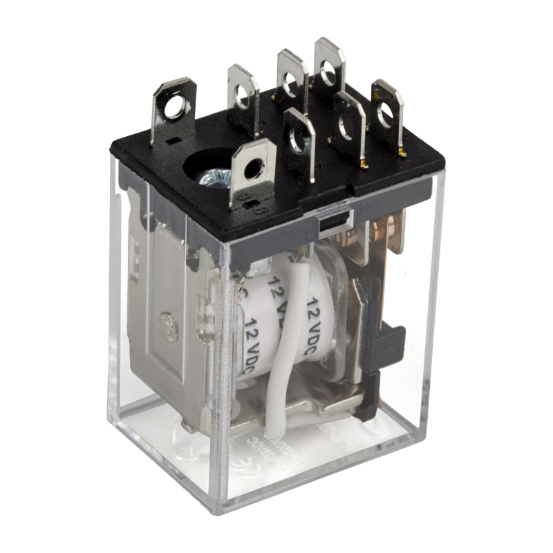 Transparent 8-Pin 10A Power Relay with PCB Quick PinThis general-purpose relay features a transparent housing for visual contact inspection, a common choice for protection equipment needing reliable switching of control circuits in phase monitoring applications.View Product →
Phase sequence monitoring
Digital phase loss relays also check the order in which the phase voltages cross zero. If the phases appear in the wrong sequence, the motor will rotate in reverse, which can damage pumps, compressors, fans and machine tools. The relay trips regardless of whether all three phases are present, which is why the same device is often called a phase failure and phase sequence relay.
Response time and reset behaviour
Response time is a key difference between protection levels. A relay that reacts in 0.1 to 0.5 seconds prevents most heat accumulation; one that needs several seconds may allow a critical temperature rise in the winding. Many relays offer an adjustable delay from 0.1 s to 10 s so that the protection can be coordinated with motor starting and other devices. The reset mode also matters: manual reset stops an unexpected restart in safety-critical plants, while automatic reset is preferred in unmanned installations.
Main Types of Phase Loss Relay and Their Differences
Phase loss relays are not all built around the same sensing method. Understanding the families helps you match the product to the fault conditions that actually exist at your site.
- Voltage monitoring relays. These connect directly to the three-phase supply and react to phase-to-phase voltage collapse. They are simple, reasonably priced, and suit the majority of motor starter applications.
- Current monitoring relays. These use current transformers and respond to current imbalance or negative-sequence current. They ignore voltage fluctuations upstream, which makes them suitable for large motors and shared busbar systems.
- Phase sequence and phase loss relays. These combine loss detection with rotation-direction supervision, which is essential for pumps, fans, compressors and lifts.
- Integrated motor protection relays. These combine phase loss, unbalance, overload, locked rotor and thermal memory in one package. They are used on critical production lines where a single device must provide comprehensive electrical protection.
| Type | Sensing input | Typical response time | Best suited to |
|---|---|---|---|
| Voltage-sensing phase failure relay | 208–480 VAC direct connection | 0.1–1 s | Standard motor starters, HVAC, small pumps |
| Current-sensing phase loss relay | 5 A current transformer secondary | 0.2–2 s | Large motors, motors on shared busbars |
| Phase sequence + loss relay | Voltage direct connection | 0.1–0.5 s | Pumps, compressors and lifts where reversal is dangerous |
| Integrated motor protection relay | Voltage + CT + temperature input | Configurable | Critical production lines, OEM equipment |
Choose the type by the failure modes you realistically face. A plant with a history of blown fuses and loose connections on the incoming supply is well served by a voltage-sensing relay. A site with long cables, fluctuating utility voltage, or several motors on one busbar will get more reliable discrimination from a current-sensing or integrated relay. For low-cost machines sold in high volumes, a simple voltage relay is often enough to satisfy the safety criteria of the target market.
Key Specifications and Phase Loss Relay Selection Criteria
When you buy relays in volume for machine building, or replace a failed unit on an existing panel, the specification list below is what you need to compare between candidates. Every one of these parameters affects whether the relay trips at the right moment and whether it survives in its environment.
| Specification | Typical value | Selection note |
|---|---|---|
| Sensing / control voltage | 208–480 VAC, 50/60 Hz | Must match the actual supply voltage. Some models accept a wide range; others need the nominal voltage applied to the sensing terminals. |
| Undervoltage trip threshold | 70–80% of nominal | Lower thresholds reduce nuisance tripping during voltage sags but give slower protection. Adjustable thresholds are recommended where supply dips are common. |
| Trip delay | 0.1–10 s | Short delays protect the motor faster. Longer delays prevent tripping during motor starting or short supply interruptions. |
| Output contact form | 1 SPDT or 1 DPDT | DPDT contacts let one contact drop the contactor while the second drives an alarm lamp or a PLC input. |
| Output contact rating | 5 A / 250 VAC or 10 A / 250 VAC | Check the VA draw of the contactor coil and keep at least 50% margin. Signal-level contacts fail early on large contactors. |
| Reset mode | Manual or automatic | Manual reset prevents unexpected restarts in safety-critical lines. Automatic reset is convenient for unattended stations. |
| Mounting style | DIN rail, panel screw, socket | Socket-mounted relays are replaced fastest in the field. Use a relay and socket from the same manufacturer to guarantee good contact. |
| Ambient temperature | -20 °C to +55 °C | Derate the relay if it is installed inside a hot control cabinet. The output relay contacts also carry an electrical life derating curve. |
Compliance marks are the first thing a purchasing engineer should check. Buyers in the European market ask for CE, buyers in North America look for UL or cUL, and the Chinese market recognizes CQC. A manufacturer holding ISO 9001, UL, TUV, CQC and RoHS compliance has already performed the qualification work that normally delays a new supplier approval in a global supply chain.
Many of the general relay selection principles that apply to control relays also apply to phase loss relays. The coil voltage, contact material and switching endurance should be chosen for the control circuit, never for the motor circuit, and the contact rating must be verified against the actual electrical life you expect.
In addition to the monitoring relay itself, a control panel often needs auxiliary power relays for cabinet heating, lighting, fan control and signaling. When these functions are designed at the same time as the protection circuit, ordering the complete relay family from one manufacturer simplifies wiring, reduces stock keeping units, and keeps the electrical life of every device consistent.
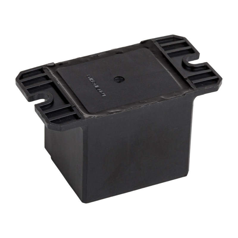 SPDT 5-Pin 30A High Power PCB RelayRated for 30A switching, this industrial-grade relay suits auxiliary functions like cabinet heating, lighting, and fan control, helping maintain consistent electrical life across panel devices.View Product →
A final warning about price-driven buying. The difference between a field-proven relay and a cheaper look-alike usually appears in contact material, coil insulation, sealing quality and calibration accuracy. A relay that trips 5% late, or with wide hysteresis, can defeat the entire purpose of protection. For a component that exists to prevent costly failures, buying on certificate and documented performance is safer than buying on price alone.
Phase Loss Relay Applications Across Industries
Phase loss relays are used in every industry that depends on three-phase motors. The application determines how the relay is set, how fast it must react, and whether automatic restart is acceptable.
Water treatment and pumping
Pump stations, irrigation systems and booster sets must not run on two phases. A phase loss relay with phase sequence detection prevents reverse rotation and dry-running damage.
HVAC and refrigeration
Chillers, fans, compressors and condensing units in commercial buildings rely on phase loss protection to avoid compressor burnouts and repeated service callouts.
Material handling
Conveyors, hoists, cranes and elevators need reliable phase protection because a sudden stop or slow-down can create safety hazards for operators and product jams on the line.
Food and beverage production
Mixers, filling lines and refrigeration tunnels run continuously. Phase loss protection helps maintain production schedules and avoids spoiled batches from an unnoticed motor failure.
| Application scenario | Selection point |
|---|---|
| Municipal or agricultural water pumping | Choose phase sequence and phase loss detection; use manual reset to prevent unexpected pump starts after a fault. |
| HVAC rooftop units and chiller plants | Select a relay with an adjustable trip delay in order to ignore the brief voltage dips caused by other starting equipment. |
| Conveyor lines in a factory | Use a DPDT output relay to run both the contactor coil and a panel alarm lamp so operators see the supply fault immediately. |
| Large motors on a shared busbar | Prefer a current-sensing relay so that protection discriminates between a real phase loss at the load and a dip in the common supply. |
OEM machine builders often standardize on one phase loss relay model across their product range, then use different sockets or terminals for different motor sizes. This approach simplifies wiring documentation, reduces spare-part inventory, and makes field service easier for the end customer maintenance team.
Phase Loss Relay Wiring and Installation Guide
Correct wiring turns a good relay into real protection. A phase loss relay whose sensing terminals are connected after a contact that opens regularly, or whose output contacts switch the wrong coil, protects nothing at all.
- Mount the relay on a DIN rail or panel inside the control enclosure, away from direct heat sources and where it can be viewed when the door is open.
- Connect the sensing terminals to the three phases before the motor contactor, so that a fault in the contactor or the motor branch is seen as a supply fault. For voltage-sensing relays, observe whether neutral is required for a 230 VAC supply.
- Wire the output contact in series with the contactor coil circuit. Use a DPDT relay if you want a second contact for the alarm circuit.
- Set the trip threshold and trip delay before energizing the motor. Start with the values given in the datasheet for the motor class, then adjust after checking the actual supply behavior.
- Select the reset mode. Manual reset is mandatory for machinery that must not restart by itself after an electrical fault, such as lifts and presses.
- Label the relay with the date of installation, the settings, and the equipment it protects. This makes routine testing faster.
Socket-mounted relays have a practical advantage in industrial installations. The relay plugs into a socket that carries all wiring, so a faulty relay can be exchanged in seconds without undoing terminals. Dust and moisture protection also improves because the base covers the connection points. This is one of the reasons why relay manufacturer catalogs offer matching sockets and relays as a set.
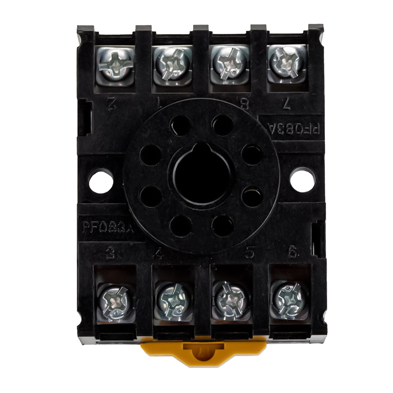 HLS-PF083A Relay Socket for MK2P RelaysThis socket allows quick relay exchange without rewiring, improving dust and moisture protection. It is designed for MK2P relays and is offered by a certified relay manufacturer.View Product →
During installation, keep the relay ambient temperature within its rated range. Relays mounted directly above power resistors, transformers, or other heat-generating components will trip later or earlier depending on the design, and the output relay contact durability is reduced by heat. Use the recommended tightening torque for the terminals, and avoid leaving loose strands of wire that can short adjacent contacts.
If the phase loss relay also protects against phase reversal, verify the motor rotation direction after first energization. A clockwise rotation label on the machine is not enough; check the actual shaft direction with the coupling guard closed.
How to Test and Maintain a Phase Loss Relay
A phase loss relay, like any protective device, can only protect if it is tested regularly. Factory calibration is not enough, because the relay has to share the panel with dust, heat, vibration and aging contacts.
Perform the following functional test at least once a year on critical installations.
- Energize the installation and verify that all three phase indicator lamps or the relay status display show normal condition.
- Open one phase of the supply to the relay manually with a switch, remove the fuse, or use a test jumper on the sensing terminals, depending on the relay design.
- Measure the time between the loss of the phase and the de-energization of the contactor. Compare it with the relay specification.
- Close the phase again, reset the relay, and check that the contactor re-energizes and the motor starts normally.
- Repeat the test for the other two phases. A relay that fails one phase but detects the other two has an internal measuring problem or a wiring fault.
- If the relay has a phase sequence function, swap two phases temporarily for the test and confirm that the relay trips.
Routine maintenance should also include checking the tightness of all terminals, cleaning the housing, and examining the output relay contacts if the relay is serviceable. A replacement relay should be stored in a clean, dry place, inside its original packaging, and tested by the site team before it is put into the store.
| Symptom | Likely cause | Handling measure |
|---|---|---|
| Relay does not trip when one phase is opened | Wrong sensing terminals, faulty internal measuring circuit, or delay set too long | Verify wiring, test each phase, replace the relay if the fault appears on all phases |
| Relay trips continuously on a healthy supply | Undervoltage threshold set too high, supply unbalance above the relay setting, or loose connections on the sensing side | Measure the actual three-phase voltage, correct the supply fault or adjust the threshold |
| Contactor does not drop out when the relay trips | Output contact welded, wiring short-circuit, or contactor coil supplied by a separate circuit | Check the contactor control circuit, replace the output relay if the contact is welded |
| Relay trips only occasionally during motor starting | Trip delay too short for the starting current and starting time of the motor | Increase the trip delay, or use a relay with a wider delay setting |
Buying Phase Loss Relay Components from a Relay Manufacturer
In the B2B market, phase loss relays rarely arrive as standalone branded boxes from a wholesaler whose only function is distribution. OEM builders and panel shops buy them from relay manufacturers who can supply the monitoring device, the output relays inside it, and the sockets used to mount them, all with consistent quality documents.
Working directly with a manufacturer gives three advantages. The first is matching: relays and sockets made by the same factory have guaranteed terminal layouts, mechanical dimensions, contact materials and electrical life. The second is certification: a manufacturer with ISO 9001, UL, TUV, CQC and CE compliance can provide the certificates that your own customers will ask for. The third is customization: OEM/ODM projects may require a different coil voltage, a different contact arrangement, or printed markings with your own brand.
When evaluating a phase loss relay supplier, ask these questions:
- Can the manufacturer supply a complete series of general-purpose power relays, automotive relays, telecom relays and relay sockets, so that your panel can be built from one qualified source?
- Are the product specifications and wiring diagrams consistent between models, so that a control panel designed around one relay family can be extended later?
- Does the factory have its own production, testing equipment and quality management system, rather than simply reselling another company products?
- How quickly can the manufacturer deliver small pilot quantities and how does it support large wholesale or distribution orders?
Ningbo Helishun Electron Co., Ltd. has manufactured relays since 2000 from an 8800-square-meter factory in Ningbo, China, and sells to more than 100 countries. Its product range covers automotive relays, general-purpose power relays, telecom relays and relay sockets, with the transparent 8-pin and 11-pin models being particularly common in protection and control panels. The company history, quality system and export experience are summarized in its company profile.
For wholesalers and distributors, a manufacturer that holds a stable range of standard products is easier to stock than one that only builds custom units. Standardized product families, clear model codes and a published sitemap of product pages let buyers check specifications before sending an inquiry, which speeds up the whole procurement cycle.
Phase Loss Relay FAQ
What is the difference between a phase loss relay and an overload relay?A phase loss relay monitors the quality of the three-phase supply and reacts to a missing phase, unbalanced voltage, undervoltage, or wrong phase sequence. An overload relay monitors motor current and protects the motor against mechanical overload, locked rotor and excessive heating. The two are complementary. A complete protection scheme for a three-phase motor normally includes both. |
Can a phase loss relay detect undervoltage and phase sequence errors?Yes, most industrial phase loss relays also include undervoltage detection. If any phase-to-phase voltage falls below the set threshold, the relay trips. Digital models also monitor phase sequence by checking the order in which the phase voltages cross zero. If a motor is connected with reversed phases, the relay trips to prevent reverse rotation, which could damage pumps, compressors and other driven equipment. |
How fast does a phase loss relay trip?Typical response times range from 0.1 seconds to 2 seconds, depending on the sensing method and the selected delay setting. Voltage-sensing relays tend to respond faster because a phase-to-phase voltage collapse is almost immediate. Current-sensing relays may need slightly longer because the current must first rise in the remaining windings. The chosen delay setting should be longer than the motor starting time to avoid nuisance tripping, yet short enough to protect the winding from heat accumulation. |
Do I need one phase loss relay for each motor?Not necessarily. Because phase loss is a supply event, one relay can protect a group of motors that share the same three-phase bus, provided that the relay output can interrupt the coil circuit of all the contactors involved. Each motor still needs its own overload relay. For critical or high-value individual motors, dedicated phase loss protection is recommended so that a fault in one branch can be identified quickly. |
How do I test a phase loss relay?The simplest test is to open one phase while the motor is running and confirm that the contactor drops out within the specified time. Repeat the test on each of the three phases. If the relay has a phase sequence function, swap two phases temporarily and confirm that the relay trips. Test procedures should be written into the plant maintenance schedule and performed at least once a year on critical machines. |
Can a phase loss relay protect a variable-frequency drive (VFD)?A phase loss relay should be installed on the line side of a VFD, monitoring the incoming supply to the drive. The output of a VFD is not a clean three-phase sine wave, so voltage-based phase loss detection on the motor side would not work correctly. Many VFDs include their own electronic output protection for single-phasing of the motor, but they cannot detect a loss of phase in the supply feeding the drive. A line-side phase loss relay closes that gap. |


