



 English
 中文简体
中文简体Content
- 1 What a Phase Monitoring Relay Actually Monitors
- 2 How the Measuring and Output Circuit Works
- 3 Selection Criteria: What to Settle Before You Order
- 4 Wiring, Setting and Commissioning
- 5 Fault Detection Timing: Reading the Bar Chart
- 6 Field Troubleshooting: The Six Faults You Will Actually Meet
- 7 Sourcing from a Manufacturer or Supplier
- 8 Comparing Alternatives: What Protects What
- 9 Frequently Asked Questions
- 9.1 What is the difference between a phase monitoring relay and a voltage monitoring relay?
- 9.2 Will a phase monitoring relay protect the motor from overload?
- 9.3 What delay should I set for phase loss and for undervoltage?
- 9.4 Does a phase monitoring relay need a separate power supply?
- 9.5 Will the relay reset automatically once the fault clears?
- 9.6 Can the output contact switch the motor directly?
- 9.7 How do I verify phase sequence is correct after maintenance?
- 9.8 Is a phase monitoring relay worth fitting on small motors?
- 10 Further Reading and Company Information
A 15 kW screw compressor drops offline because one phase of the incoming supply has failed upstream at a fuse. The motor does not stop politely. It keeps trying to run on two phases, drawing locked-rotor current through the remaining windings, until the thermal protection finally trips or the winding insulation gives out. The real cost is not the motor. It is the two weeks of production lost while a replacement is sourced. This is precisely the failure a phase monitoring relay is built to prevent, and it is the reason the device sits in control panels from water treatment plants to packaging lines.
The conclusion up front: a phase monitoring relay is one of the cheapest protective devices you can add to a three-phase control circuit, and one of the most frequently omitted. It measures the three line voltages continuously, compares them against thresholds, and takes its output relay out of circuit within milliseconds when a phase parameter goes outside limits. It does not protect the motor from overload, and it does not replace a thermal relay. What it does is remove the voltage-side causes that overwhelm thermal protection before it can respond.
This guide covers what these relays actually monitor, how the internal measuring circuit decides to trip, how to select and set one, where they sit in a panel, how to troubleshoot nuisance trips, and what to check when you buy from a manufacturer or supplier. It is written for panel builders, electrical designers, maintenance engineers and procurement teams who specify three-phase protection for machines that cannot afford to run on bad power.
What a Phase Monitoring Relay Actually Monitors
The name is slightly misleading, because a modern phase monitoring relay rarely monitors only one thing. Most units on the market supervise a set of parameters simultaneously and act on whichever limit is crossed first. Understanding which parameters matter to your application is the first step in choosing the right device, because a relay that supervises six things costs more than one that supervises two, and the extra functions may never be needed.
Phase loss and phase failure
Phase loss is the most common reason engineers specify a monitoring relay. It occurs when one or two of the three phases disappears - a blown fuse, a loose terminal, a broken conductor, a failed pole in an upstream breaker, or a contact that has burned open. A three-phase induction motor running on two phases cannot produce a rotating field, so it stalls, draws three to eight times its rated current, and heats rapidly. The magnitude of the danger depends on load: a lightly loaded motor may continue turning and simply overheat more slowly, which is more dangerous because the failure is silent.
Detection is straightforward. The relay measures each phase-to-phase voltage and compares it against a minimum threshold. If any pair falls below that threshold for longer than the set delay, the output drops out.
Phase sequence and phase reversal
Phase sequence monitoring checks that the three phases arrive in the expected order, normally L1-L2-L3 rotating clockwise. If two supply conductors are swapped during maintenance, during a transformer replacement, or at a temporary connection point, the motor runs backwards. For a pump, that means no flow or reverse flow. For a screw compressor, it can mean no oil pressure and rapid mechanical damage. For a conveyor feeding a crusher, it means material goes the wrong way into a blocked chute.
Sequence detection inside the relay is usually done with a small RC phase-shifting network. Each phase is sampled through a different resistor-capacitor combination, producing a timing pattern that only appears in the correct order. If the pattern is inverted, the relay refuses to energise - or drops out immediately if it was already running.
Voltage imbalance and asymmetry
Imbalance is the silent killer. A three-phase motor supplied with a 2 percent voltage imbalance will run with a winding temperature rise roughly equivalent to an 8 to 12 percent current imbalance, because negative-sequence current flows in the stator and does almost no useful work. The rules of thumb vary between motor standards, but the direction is always the same: small voltage imbalance, large thermal penalty. Imbalance monitoring gives an early warning long before a winding actually fails.
Overvoltage and undervoltage
Undervoltage causes motors to draw more current for the same mechanical output, and contactors to chatter on their holding coils. Overvoltage stresses insulation and increases no-load losses. Both are slow-developing compared with phase loss, so the relay usually applies a longer delay - often adjustable from 0.1 to 10 seconds - to ride through the dip caused by a large motor starting elsewhere on the same busbar.
Neutral displacement and frequency
Some advanced models also watch for neutral conductor failure or neutral-to-earth voltage drift, which is relevant where single-phase loads share a four-wire system with three-phase motors. A smaller number include a frequency window, useful for generator-supplied installations where the prime mover can drift out of tolerance.
| Parameter | Typical cause | Consequence if unsupervised | Detection method |
|---|---|---|---|
| Phase loss | Blown fuse, loose terminal, broken conductor | Stalled motor, locked-rotor current, burnt winding | Per-phase voltage comparison against minimum threshold |
| Phase sequence | Swapped conductors after maintenance or transformer work | Reverse rotation, pump dry-run, mechanical damage | RC phase-shift timing pattern |
| Voltage imbalance | Uneven single-phase loading, poor supply quality | Elevated winding temperature, reduced insulation life | Comparison of the three phase voltages against each other |
| Undervoltage | Long feeder, heavy upstream load, weak transformer | High current draw, contactor chatter | Comparison against adjustable lower set point with delay |
| Overvoltage | Light loading on a long line, capacitor switching | Insulation stress, increased losses, tripped drives | Comparison against adjustable upper set point with delay |
| Neutral displacement | Open neutral in a four-wire distribution system | Voltage swings across single-phase loads, equipment damage | Neutral-to-earth voltage comparison |
How the Measuring and Output Circuit Works
Understanding the internal signal path helps you set delays sensibly and diagnose odd behaviour later. A phase monitoring relay is not a mysterious device. It is a small analogue or digital measuring instrument with a relay bolted to its output stage, and every trip it makes follows the same sequence of steps.
Step one: scaling the line voltage down
The three phases are connected through a resistive divider network or a small measuring transformer. Fifty years ago this was almost always a transformer with three primary windings; today most manufacturers use a high-value resistor chain with optical or capacitive isolation, which reduces cost and eliminates the saturating behaviour of small transformers during severe voltage dips. After scaling, each phase sits at a low-level AC signal - typically a few volts - that the measuring electronics can handle safely.
Step two: rectification and filtering
Each scaled phase is rectified and smoothed so it becomes a DC level proportional to the RMS line voltage. A filter with a time constant of a few tens of milliseconds removes the worst of the harmonic content and prevents the comparison stage from reacting to individual waveform peaks. This filtering is also where the first part of the response time budget is spent.
Step three: comparison against references
The smoothed DC levels feed a set of comparators. One comparator checks each phase against the minimum threshold. Another compares the three phases to each other to derive an imbalance figure. Two more compare the average against adjustable upper and lower voltage set points, usually via trimmer potentiometers or digital menu settings. The phase sequence detector operates in parallel, using the RC network described earlier.
Step four: delay and decision logic
Raw comparator output is far too fast for practical use. A motor starting directly on line will pull the terminal voltage down for hundreds of milliseconds, and a capacitor bank switching in nearby will produce a transient that looks exactly like a voltage collapse. The delay circuit holds each fault condition for a defined period before acting on it, and the relays are designed so that genuine phase loss is caught almost immediately while voltage excursions are allowed a longer window.
Step five: the output relay
Finally, the decision logic drives the coil of a small electromechanical relay, almost always a single-pole changeover or two-pole changeover contact rated for a few amps at 250 V AC. In the healthy state the coil is energised and the contact is closed, feeding the downstream control circuit. Any detected fault de-energises the coil, the contact opens, and the motor contactor drops out. This "fail-safe" arrangement means a loss of auxiliary supply to the monitoring relay itself also removes the motor from service, which is generally the behaviour you want.
Why the output contact is not the motor contactor
A common design error is to assume the monitoring relay's output contact can switch the motor load directly. It cannot and should not. Its contact rating exists to switch a contactor coil or a small pilot relay, not a 15 kW motor. In panels where the monitoring relay drives several circuits, or where the control voltage differs from the monitoring supply, an interface relay is inserted between the two.
This is the point where panel builders often standardise on a plug-in interface relay and a matching socket, so that a failed contact can be swapped in seconds without disturbing wiring.
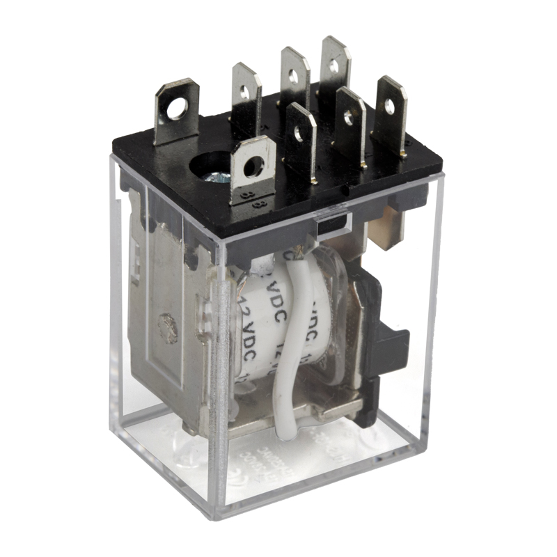 transparent 8PIN 1C 16A 20A power relay PCB QUICK PIN HLS-13F-1Max Switching VoltageView Product →
The companion socket is a practical necessity rather than a luxury. Screw-terminal sockets allow the relay to be changed without touching the field wiring, and they simplify testing during commissioning because the relay can be pulled and the control circuit proven independently.
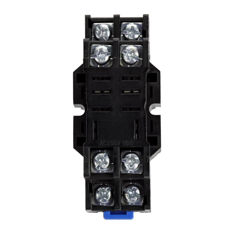 HLS-PTF08A-01 relay socket for 13F-1 or 13F-2Ningbo Helishun Electron Co.,Ltd.View Product →
Selection Criteria: What to Settle Before You Order
Most selection mistakes come from leaving one of five parameters unresolved until after the purchase order is placed. Work through them in order and the choice usually narrows to two or three models.
Nominal system voltage and monitoring range
Three-phase systems exist at 200 V, 220 V, 380 V, 400 V, 415 V, 440 V and 480 V in different regions, at 50 or 60 Hz. The monitoring relay must be specified for the correct nominal voltage and must have a measurement range wide enough to accommodate the normal tolerance band - typically plus or minus 10 percent - without sitting permanently at the edge of its window. A relay set at exactly 400 V nominal will nuisance-trip on a supply that routinely sits at 415 V.
Which parameters you actually need
A relay that monitors phase loss and sequence only is cheaper, smaller and less likely to nuisance-trip than a full four-function unit. Add overvoltage, undervoltage and imbalance supervision only where the load justifies it. Large motors, submersible pumps, refrigeration compressors and equipment fed from a weak rural supply justify the full function set. Control panels full of small contactors and indicator lamps usually do not.
Delay range and adjustment method
Fixed-delay units are simpler and cheaper. Adjustable units give you the flexibility to match the relay to the installation. Whichever you choose, the delay must be long enough to ride through a legitimate voltage dip caused by a nearby motor start, and short enough to disconnect before thermal damage accumulates. As a starting point, phase loss delays of 0.1 to 0.5 seconds and voltage delays of 1 to 5 seconds cover a large proportion of industrial installations.
Output contact configuration and rating
Check the contact form - one changeover or two - and the rating. A 5 A at 250 V AC contact will happily drive a contactor coil or a PLC input, but not three contactor coils in parallel. Where the monitoring relay must signal a PLC while also breaking the motor circuit, two changeover contacts are worth the extra cost. Confirm whether the contact is rated for the control voltage you use; DC control circuits in particular require a contact with adequate DC breaking capacity, which is often much lower than the AC rating on the same device.
Mounting, width and auxiliary supply
DIN rail mounting dominates industrial panels. Width matters because panel space is finite: modular monitoring relays are typically 17.5, 22.5 or 35 mm wide. Some units are self-powered from the monitored voltage; others need a separate auxiliary supply, which adds terminals, wiring and a failure point. Plug-in versions on an eight-pin or eleven-pin base offer the fastest replacement, which matters in continuous-process plants.
Environment and certification
Panel interiors reach 55 to 60 degrees Celsius in summer, and monitoring relays are often the first devices to drift. Check the ambient temperature rating. For panels exported to North America, look for UL recognition; for Europe, CE marking with a declaration of conformity; for global OEM programmes, TUV and RoHS documentation as well.
- Confirm nominal voltage, frequency and expected tolerance band.
- Decide which parameters must be supervised and which are optional.
- Choose fixed or adjustable delay, and a range that matches the load.
- Select contact form and rating based on what the output must drive.
- Verify rail width, auxiliary supply requirement and replacement strategy.
- Check ambient rating, ingress protection and export certifications.
- Confirm the voltage threshold settings are within the supply's normal operating window.
- Decide whether a matching socket or interface relay is needed for maintainability.
Wiring, Setting and Commissioning
A correctly chosen relay installed incorrectly gives no protection at all, and the most common installation error is a matter of position rather than wiring technique.
Where to tap the voltage
The monitoring relay must sense the incoming supply, upstream of the motor contactor. If it senses downstream of the contactor, it sees nothing when the motor is stopped and loses sight of the incoming supply the moment the contactor opens - which is exactly when an upstream phase loss would go unnoticed until the next start attempt. The correct arrangement is a fused tap from the incoming terminals to the relay's measuring inputs, independent of the contactor.
Protecting the measuring circuit
Voltage sensing conductors are small and easily damaged. Protect them with individual fuses or a three-pole miniature circuit breaker sized for the conductor, not for the relay. Label them clearly as measuring circuits. In panels with multiple motors, never daisy-chain voltage sensing from one monitoring relay to another; each should have its own protected tap.
Interlocking the control circuit
The changeover contact is wired in series with the contactor coil circuit, using the normally open path so that a de-energised relay prevents starting. Where the panel also has a start-stop pushbutton station, the monitoring contact sits between the start button and the coil, so that pressing start does nothing until the supply is proven healthy. This gives operators an immediate visual clue - the motor simply will not start - rather than a mysterious trip five seconds into the run.
Setting the delay values
Set the phase loss delay short, typically 0.2 to 0.5 seconds, because genuine phase loss produces no useful operating condition and no benefit comes from waiting. Set voltage delays longer, in the 1 to 5 second range, to ride through the dips caused by other loads starting. On sites with automatic power factor correction, transient voltage rise from capacitor switching can exceed the overvoltage threshold for a few tens of milliseconds, so a delay shorter than 0.5 seconds will cause repeated nuisance trips.
Proving phase sequence after maintenance
After any work that involves disconnecting supply conductors, the sequence must be proven before the motor is run under load. The safest procedure is to jog the motor briefly with the driven equipment uncoupled, or to use a phase sequence indicator at the incoming terminals as a cross-check. Do not assume that because the monitoring relay shows healthy, the sequence is correct for a specific machine - some installations deliberately reverse two phases to obtain the correct rotation, and that decision must be documented on the panel drawing.
Documenting the settings
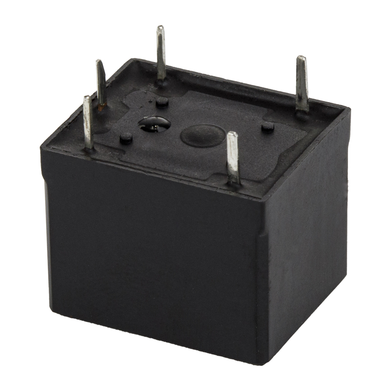
Record the set points and delay values inside the panel door, together with the date and the engineer's name. When a relay is replaced five years later, the replacement should not be set by trial and error. Where the control board itself carries an output relay - for example, a small relay soldered onto a monitoring module or a custom controller board - specify a part with a defined contact rating and a documented mechanical life.
 hot selling SPDT 5PIN 7A 10A mini power relay T73 PCB PIN HLS87 A 2 5 0VAC/ 30 VDC 10A 250 VAC/ 30 VDC 15 A 12 0VACView Product →
Fault Detection Timing: Reading the Bar Chart
The three-phase parameters differ enormously in how quickly they cause damage, and that difference is the reason monitoring relays allow different delays for different fault types. Getting the timing right is a balance between protecting the machine and avoiding nuisance trips that operators will eventually bypass.
A phase sequence error produces no useful operation at all, so there is no reason to wait before acting on it. A single-phase loss on a loaded motor raises current dramatically within a few cycles, so the response window is short but not instantaneous. Voltage imbalance develops its thermal effect over minutes and hours, which means a somewhat longer window is acceptable and often desirable. Neutral displacement is slower still, and rarely produces damage in under a second. The chart below shows indicative detection windows that reflect these differences.
The values are representative magnitudes, not specifications for any particular model. Actual response times depend on the relay design, the filtering used, the delay setting and the severity of the fault event itself. Use the comparison to understand the relative order of magnitude, then confirm the real figures against the datasheet of the device you intend to install.
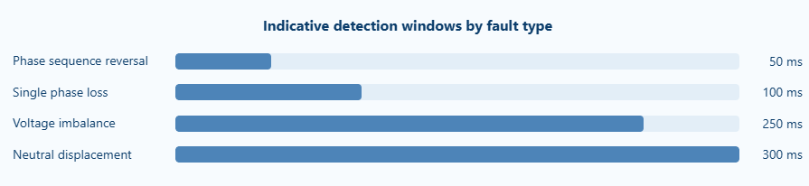
The chart makes a simple point visible: the faults that destroy a motor fastest are the ones that need the shortest response window, and the faults that develop slowly are the ones where a longer window pays off in reduced nuisance tripping. Phase sequence reversal sits at the fast end because there is no operating condition in which a reversed motor is preferable to a stopped one. The relay should refuse to close its output contact until the sequence is proven correct, which in practice means the detection window is the time taken for the internal comparison circuit to settle, not a deliberately applied delay.
Single phase loss occupies the next position. A loaded three-phase motor loses its rotating field when one phase disappears, and the remaining two windings carry the full mechanical load. Current rises to several times rated value within a few electrical cycles. A hundred milliseconds is roughly the point at which the relay has enough information to be certain the loss is real rather than a measurement artefact, and it is well within the thermal capability of a properly protected motor. Shortening this further brings little benefit and increases the chance of tripping on a genuine but harmless transient.
Voltage imbalance sits nearly a third of the way along the scale, and the position is deliberate. Imbalance develops its damaging effect through sustained elevated winding temperature. A few hundred milliseconds of imbalance during a switching event causes no measurable harm, so the relay can afford to average the measurement over a longer period, which improves accuracy and rejects noise on the supply.
Neutral displacement occupies the longest window. In a four-wire system, transient neutral voltage excursions occur whenever large single-phase loads switch, and a fast-acting detector would trip constantly. Because the consequence of neutral displacement develops over seconds and minutes rather than cycles, a longer window costs nothing in protection terms.
Two practical conclusions follow from the pattern. First, do not set all delays to the same value; the relay exists to distinguish between events that need different responses. Second, when nuisance trips occur, resist the temptation to lengthen every delay. Identify which parameter is tripping, and adjust only that one. A phase loss delay lengthened to several seconds to cure a spurious imbalance trip removes most of the protection you paid for.
It is also worth noting that the response figures above describe detection, not total system reaction. Once the monitoring relay decides, its output contact must open, the contactor coil must de-energise, the contactor must open and the motor current must decay. On a large contactor this mechanical sequence can add 30 to 80 milliseconds. In a system where the whole point is speed, the contactor matters as much as the relay.
Field Troubleshooting: The Six Faults You Will Actually Meet
Once a panel is in service, the questions change. It is no longer about selection and more about why a device that worked last month is now tripping every afternoon.
Nuisance tripping with apparently healthy supply
If a monitoring relay trips while a multimeter reads a perfectly balanced supply, the cause usually lies in something a multimeter cannot see. Voltage imbalance of 2 to 3 percent is invisible on a display that rounds to whole volts, but it is enough to cross an imbalance threshold set too tightly. High harmonic content from variable speed drives on the same busbar distorts the waveform and shifts the RMS measurement. Check with a power quality analyser before adjusting thresholds, because raising a threshold to cure a symptom can hide a genuine supply problem.
Tripping only when another load starts
This is a delay problem, not a detection problem. A large direct-on-line motor starting nearby pulls the terminal voltage down for 200 to 600 milliseconds. If the undervoltage delay is shorter than that, the monitoring relay will drop out every time the neighbour starts. Increase the undervoltage delay into the 1 to 3 second range and confirm the magnitude of the dip first.
Relay does not trip on genuine phase loss
Almost always a wiring position error. The sensing conductors have been taken from the load side of the contactor, or from a point downstream of the isolation device that opens when the motor stops. Verify the tap point on the drawing and confirm with the panel dead that the sensing circuit is continuous back to the incoming terminals.
Output contact welded closed
A welded contact means the output has been asked to switch more than its rating, or it has switched an inductive DC load without adequate suppression. Check what is actually connected downstream. If a contactor coil is being driven, confirm whether the coil is AC or DC and whether the contact rating covers that case. Adding an RC suppressor across an AC coil or a flywheel diode across a DC coil dramatically extends contact life.
Relay resets but motor will not start
Check whether the unit is set to manual reset. Many monitoring relays latch the fault and require a front-panel reset button or an interruption of the auxiliary supply. Operators unfamiliar with the device will report "the motor will not start" when the actual condition is "the relay is waiting to be reset". Documenting the reset procedure inside the panel door prevents a lot of unnecessary callouts.
Look at ambient temperature inside the panel first. A monitoring relay rated to 55 degrees Celsius that sits above a variable speed drive in a sealed enclosure will drift as the afternoon heats up. Check the actual internal temperature with a data logger rather than estimating. If the panel interior exceeds the device rating, add ventilation or relocate the device.
Sourcing from a Manufacturer or Supplier
Procurement decisions for protective relays are rarely made in isolation. The same purchase order usually covers contactors, terminal blocks, interface relays and sockets, and consolidating suppliers reduces administrative overhead and inbound inspection effort.
Technical questions worth asking
- What is the exact measured voltage range, and does it cover the normal tolerance band of the supply?
- What are the factory default set points, and how are they changed?
- Is the output contact rated for the control voltage and load type in your panel?
- What is the ambient temperature rating, and does it include a derating curve?
- Is the device self-powered or does it require an auxiliary supply?
- How is phase sequence detection implemented, and what happens during a severe voltage dip?
Documentation and certification
Export panels need evidence, not assurances. Ask for the declaration of conformity, the UL file reference where applicable, the RoHS statement and the type test report covering dielectric strength and impulse withstand. A supplier who cannot produce documentation on request is a supplier who will cost you time at the customs stage or at the customer's factory acceptance test.
Compatibility with existing installations
Many panels are not new builds. They are upgrades, retrofits or replacements of equipment from a supplier that no longer exists. In those cases, physical compatibility matters as much as electrical specification: the same rail width, the same terminal arrangement, the same measuring input positions. Chinese relay manufacturers have spent two decades building product lines around exactly this requirement, deliberately keeping terminal layouts and mounting dimensions consistent with established international footprints so that a replacement drops into an existing panel without redrilling.
Ningbo Helishun Electron Co., Ltd., trading under the HELISHUN brand, has manufactured relays and relay sockets from its Ningbo facility since 2000, with a product range covering general purpose power relays, automotive relays, telecom relays and matching sockets. The company holds UL, TUV, CE, CQC and ISO 9001 certification and supplies OEM and ODM partners across more than 100 countries. For panel builders assembling three-phase control circuits, the relevant parts of that range are the interface relays and sockets that sit downstream of a monitoring device and switch contactor coils, indicator circuits and PLC inputs.
Evaluating total cost rather than unit price
A protective relay that costs twice as much but eliminates one unplanned motor failure over its service life has paid for itself many times over. The evaluation should include the cost of a motor rewind, the production lost during the outage, the labour to diagnose the fault and the expedited freight for a replacement. Against those numbers, the difference between a cheap relay and a properly specified one is negligible.
Comparing Alternatives: What Protects What
Phase monitoring relays are sometimes proposed as a replacement for other protective devices, and sometimes dismissed as unnecessary because "the drive already has protection". Neither position is correct. Each device in a motor circuit covers a different failure mode, and the overlap is smaller than it appears.
| Device | Primary protection | Detects phase loss | Detects phase reversal | Detects voltage faults |
|---|---|---|---|---|
| Phase monitoring relay | Supply quality | Yes, within milliseconds | Yes | Yes, adjustable set points |
| Thermal overload relay | Motor current and thermal model | Eventually, by thermal action | No | No |
| Electronic motor protection relay | Current, thermal model, some voltage | Yes, via current asymmetry | Only if voltage sensing is fitted | Model dependent |
| Variable speed drive | Motor current, DC bus, internal faults | Yes, internal to the drive | Usually ignored | Limited window, drive may trip |
| Phase sequence indicator | Nothing - it is a test instrument | No | Indicates only, no output | No |
The key distinction is between current-based and voltage-based protection. A thermal overload relay watches current and responds when the motor has already begun to overheat. An electronic motor protection relay does the same thing with more accuracy and a better thermal model. Both of them react to a fault that has already started to affect the motor. A phase monitoring relay reacts to the supply condition before the motor is affected at all - and in the case of phase reversal, before the motor has even started.
Where a variable speed drive is fitted, the drive itself supervises its input supply to a degree, and in many installations this is enough. But drives are not always powered up when the panel is energised, and a monitoring relay upstream of the drive provides protection during the periods when the drive is isolated or in a fault state. There is also a practical argument: a monitoring relay costs a fraction of a drive, and it keeps the supply fault separate from the drive fault in the alarm log, which shortens troubleshooting considerably.
Frequently Asked Questions
What is the difference between a phase monitoring relay and a voltage monitoring relay?
A voltage monitoring relay typically supervises a single-phase supply or the average of a three-phase supply against over and under voltage limits. A phase monitoring relay supervises the relationship between phases as well - whether all three are present and whether they arrive in the correct order. On a three-phase motor circuit, only a phase monitoring relay can detect phase loss and reversal reliably.
Will a phase monitoring relay protect the motor from overload?
No. It protects against supply-side faults. Overload, jam, single phasing caused by a mechanical fault inside the motor, and bearing failure are all current-based conditions that require a thermal overload relay or an electronic motor protection relay. A complete motor circuit normally includes both.
What delay should I set for phase loss and for undervoltage?
Phase loss can be set short, in the 0.1 to 0.5 second range, because there is no operating condition in which a motor should continue running on two phases. Undervoltage needs a longer window, typically 1 to 5 seconds, to ride through the dip caused by a large motor starting elsewhere on the same supply. Measure the actual dip duration before choosing the value.
Does a phase monitoring relay need a separate power supply?
Many models are self-powered from the monitored voltage and need no auxiliary supply. Others require 24 V DC or 230 V AC auxiliary power. Self-powered units are simpler and eliminate one failure point, but they lose function entirely when the monitored supply is completely dead - which is usually acceptable, since there is nothing left to protect.
Will the relay reset automatically once the fault clears?
Most units offer both automatic and manual reset, selectable by a switch or a menu setting. Automatic reset is convenient for remote, unmanned installations. Manual reset is safer where an operator needs to inspect the machine before restarting, and it prevents a motor from restarting unexpectedly after a supply transient.
Can the output contact switch the motor directly?
No. The output is designed to switch a contactor coil or a pilot relay, typically rated at a few amps. Switching a motor load through it will destroy the contact in a short time. If the control circuit requires more capacity than the monitoring relay provides, insert an interface relay between the two.
How do I verify phase sequence is correct after maintenance?
Use a phase sequence indicator at the incoming terminals before energising the motor, and jog the motor briefly under no load to confirm rotation direction. If the motor is coupled to a pump or compressor that cannot be run dry, use the indicator alone and cross-check against the panel drawing, which should record any deliberate phase transposition.
Is a phase monitoring relay worth fitting on small motors?
It depends on the consequence of failure rather than motor size. A 1.5 kW pump in a remote water treatment plant where a callout takes four hours is a strong candidate. A 1.5 kW fan in a workshop where a replacement is on the shelf is not. The decision should be based on downtime cost, not on nameplate power.
Three-phase motors fail for many reasons, but the ones that arrive through the supply - a lost phase, a reversed sequence, a sustained voltage excursion - are the ones that cannot be corrected by better maintenance. They arrive from outside the panel, and the only defence is to detect them before the motor is affected. A phase monitoring relay does that job for a small fraction of the cost of a single rewind, and it does it continuously, without an operator needing to notice anything.
Get the selection right, sense the supply upstream of the contactor, set the delays to match the physics of each fault type, and document what you set. Those four steps cover the overwhelming majority of what goes wrong in practice. Pair the relay with interface relays and sockets that are rated for the job, keep spare parts on the shelf, and the circuit becomes genuinely reliable rather than nominally protected.


