



 English
 中文简体
中文简体Content
- 1 What a Power Monitoring Relay Actually Does
- 2 Inside the Enclosure: The Signal Chain from Sensor to Contact
- 3 Common Types of Power Monitoring Relay and What Each One Is For
- 4 Reading the Datasheet: Twelve Numbers That Decide the Purchase
- 5 Setting Thresholds and Trip Delays Without Creating Nuisance Trips
- 6 The Output Stage: Why the Electromagnetic Relay Behind the Contact Matters
- 7 A Step-by-Step Selection Walkthrough
- 8 Application Scenarios and Typical Settings
- 9 How a Power Monitoring Relay Compares with Other Devices
- 10 Installation, Wiring and Commissioning Notes
- 11 Maintenance and Troubleshooting
- 12 Buying Considerations: Manufacturer, Supplier or Wholesaler
- 13 Frequently Asked Questions About Power Monitoring Relays
- 13.1 What is the difference between a power monitoring relay and a voltage monitoring relay?
- 13.2 Can a power monitoring relay replace a thermal overload relay?
- 13.3 Why does my relay trip whenever the neighbouring machine starts?
- 13.4 Can the output contact drive a contactor coil directly?
- 13.5 What is the correct trip delay for phase loss?
- 13.6 Do I need a current transformer?
- 13.7 Which approvals should I request before placing an order?
- 13.8 Should I choose auto reset or manual reset?
- 13.9 Can the same relay be used on a single-phase supply?
- 13.10 How do I test a monitoring relay after installation?
- 14 Continue Reading on This Site
Three nuisance trips in one week, a 15 kW pump starter that refuses to stay online, and a maintenance log showing nothing wrong with the motor: this is the classic signature of a supply-side problem that no thermal overload relay can see. Voltage sag during the afternoon shift, a single phase lost when a fuse opens, a reversed rotation after a reconnection, or one phase drifting high while the other two sit low. None of these appear on an overload curve, and all of them shorten the life of the equipment they feed. A power monitoring relay exists to catch those conditions before the damage is done.
A power monitoring relay is a panel-mounted or DIN-rail device that continuously measures the supply it is wired to, compares each measured value against an adjustable threshold, waits for a configurable delay, and then switches an output contact. In most installations the relay measures voltage, and in many it also measures current and frequency. That output contact is what the rest of the control system reacts to: it drops a contactor coil, blocks a start command, closes an alarm circuit, or hands a clean dry contact to a PLC input.
The important distinction is what the device does not do. A power monitoring relay supervises the quality of the supply feeding a load. It does not clear a short circuit, it does not measure winding temperature, and it does not replace a circuit breaker or a thermal overload. It protects the decision to run the equipment, which is a different job from protecting the equipment itself.
For panel builders, machine OEMs, system integrators and importers, the practical questions are always the same. Which quantities must be monitored, what accuracy is realistic in a real plant, how long the trip delay should be, how much current the output contact can carry without welding, and which approvals the destination market will ask for at customs. This guide answers those questions in order, from the internal signal chain through to the purchase order and the spare parts list.
A power monitoring relay turns supply quality into a switching decision, so its value is measured in avoided downtime rather than in the price of the box itself.
What a Power Monitoring Relay Actually Does
A power monitoring relay is defined by what it watches. Most industrial versions watch several quantities at once, which is why the same unit is described as a voltage monitoring relay, a phase failure relay or a phase sequence relay depending on which function the buyer happens to care about. The measurement list below is the one that matters when you compare two datasheets side by side.
- Phase-to-neutral and phase-to-phase voltage, measured as true RMS rather than as a simple average.
- Phase loss, sometimes called single phasing, which is the most damaging common fault on a three-phase motor.
- Phase sequence, the rotation direction that decides whether a motor turns the correct way after a reconnection.
- Voltage asymmetry, usually expressed as the percentage difference between the highest and the lowest phase voltage against the average.
- Overvoltage and undervoltage at independently adjustable thresholds, often with separate delays.
- Overcurrent and undercurrent, where undercurrent is frequently used as a dry-run signal for pumps and screw feeders.
- Current unbalance, which detects load-side problems such as a failing winding or a loose terminal.
- Frequency deviation and, on generator changeover panels, the rate of change of frequency.
- On larger multifunction units, true power, power factor and a simplified thermal model of the motor.
Not every project needs all of these. A single-phase packaging machine may only need overvoltage and undervoltage, because the supply is simple and the load is small. A three-phase submersible pump needs phase loss, phase sequence, asymmetry and undercurrent together, because that combination covers both supply faults and a dry running impeller without adding a separate sensor to the pump column.
It is worth separating three device families that are often confused in tender documents. A power monitoring relay watches the supply and switches a contact. A protection relay, such as a thermal overload or an electronic motor protection device, watches the load and its thermal state. A measurement transducer converts voltage or current into a 4 to 20 mA signal for a PLC but does not switch anything at all. Many modern devices combine monitoring and protection, and that is where the specification conversation usually begins.
Decide first which quantities the application genuinely needs; every additional monitored quantity adds a setting, a commissioning step and a potential source of nuisance tripping.
Inside the Enclosure: The Signal Chain from Sensor to Contact
The measurement path inside a monitoring relay is short and predictable, which is useful when you are trying to predict how a specific model will behave on a noisy plant supply. The sequence below is typical of three-phase units sold into industrial panels.
- Input scaling. Mains voltage is divided down by a resistor network or stepped down by a small transformer, while current is sensed by a current transformer or a shunt.
- Rectification and true RMS conversion. The signal is sampled and processed so that distorted waveforms from variable frequency drives still read correctly.
- Analog to digital conversion. Sampling is fast enough to detect a missing half cycle within a few tens of milliseconds.
- Comparison. A microcontroller compares each measured value with the setpoint and applies hysteresis so the unit does not chatter at the threshold.
- Delay timing. The fault must persist for the configured delay before the output changes state.
- Output drive. A small transistor switches the coil of the internal output relay.
- Contact switching. The output relay contacts open or close the external control circuit.
- Indication and reset. Front LEDs identify the fault type, and the reset logic decides whether the unit returns automatically or stays latched until an operator intervenes.
Step seven is the one buyers can influence most directly, and it is also the step most often overlooked during component sourcing. The measurement chipset inside a monitoring relay changes slowly between generations, but the output relay is a mechanical component with a defined electrical life, a defined contact material and a defined coil power, and those three numbers decide whether the unit survives ten years in a dusty control cabinet or fails in the second summer.
Hysteresis deserves a sentence of its own. If a supply hovers exactly at the threshold, a relay without hysteresis will switch in and out several times per second, which destroys both the output contact and the contactor it drives. A fixed hysteresis of two to five percent of the setpoint is enough for most installations, and an adjustable one is worth paying for on generator panels where the voltage is never perfectly stable.
Reset logic is the second behavioural setting that panel builders should read carefully. Auto reset returns the output to normal when the measured value comes back inside the window for a set period. Manual reset requires a button press or a remote signal, which prevents a machine from restarting unattended after a fault. Memory function keeps the fault indication visible even after the supply recovers, which shortens the next troubleshooting session considerably.
The measurement chain changes little between brands, but the output relay, the hysteresis setting and the reset logic are where a specification is genuinely won or lost.
Common Types of Power Monitoring Relay and What Each One Is For
The market splits into a handful of families, and each family maps to a different panel layout and a different purchasing pattern. The table below summarises the practical differences before the individual types are discussed.
| Type | What it measures | Typical application | Output |
|---|---|---|---|
| Single-phase voltage monitoring relay | One phase voltage, over and under | Small machines, single-phase feeders, compressors | One changeover, 5 to 10 A |
| Three-phase voltage monitoring relay | Three voltages, phase loss, sequence, asymmetry | Motor feeders, pumps, fans, HVAC plant | One or two changeover |
| Current monitoring relay | One or three phase currents, unbalance | Conveyors, jamming detection, pump dry run | One changeover |
| Multifunction motor monitoring relay | Voltage, current, asymmetry, sequence, thermal model | Critical motors, process lines, chillers | Two changeover |
| Frequency monitoring relay | Frequency, rate of change of frequency | Generator changeover, solar inverters, islanding | One or two changeover |
| Insulation monitoring relay | Insulation resistance to earth | IT systems, charging stations, medical areas | One changeover |
Single-phase voltage monitoring relays are the simplest and the cheapest, and they are usually bought in volume by appliance and small machine manufacturers. Three-phase voltage monitoring relays are the workhorses of industrial panels and account for the largest share of units sold through electrical wholesalers. Current monitoring relays are often specified late in a project, after a jam or a dry-run incident has already cost production time. Multifunction units appear on larger motors where the cost of a stoppage justifies a higher device price.
Frequency monitoring relays serve a different market entirely, largely generator and renewable energy panels, where the relay has to detect a drift away from the nominal frequency quickly enough to separate a generator from a grid that has already failed. Insulation monitoring relays are the most specialised of the group and are usually specified by the electrical safety engineer rather than by the panel builder.
Mounting format cuts across all six families. DIN-rail mounting dominates new panels, while panel mounting with a screw terminal cover remains common in retrofit work and in markets where the original installation dates from the 1990s. Width matters more than it looks on a drawing: a 17.5 mm unit and a 52.5 mm multifunction unit occupy very different amounts of rail, and rail space is the constraint that usually forces a redesign late in a project.
Match the relay family to the fault you have actually experienced, not to the longest feature list on the quotation.
Reading the Datasheet: Twelve Numbers That Decide the Purchase
Datasheets from different suppliers use different orders and different wording, which makes comparison harder than it should be. The twelve parameters below cover almost every decision that appears during selection, and they are worth extracting into a single comparison sheet before any sample is ordered.
| Parameter | Common range | Why it matters |
|---|---|---|
| Auxiliary supply | 24 V DC, 110 to 240 V AC/DC | Determines whether a separate panel supply is needed |
| Measuring range | Up to 300 V line to neutral, up to 520 V line to line | Direct connection versus voltage transformer |
| Setting accuracy | Plus or minus 1 to 5 percent of setpoint | Balance between nuisance trips and missed faults |
| Hysteresis | 2 to 5 percent, fixed or adjustable | Prevents contact chatter near the threshold |
| Trip delay | 0.1 to 10 s for voltage, up to 60 s for current | Ride-through on short dips versus fast protection |
| Reset mode | Auto, manual, with or without memory | Restart policy after a fault |
| Output contact | One or two changeover, 5 to 16 A at 250 V AC | Direct contactor drive versus interposing relay |
| Contact material | Silver nickel, silver tin oxide, silver cadmium oxide | Arc erosion and service life under inductive load |
| Electrical life | Around 100,000 operations at rated load | Maintenance interval and spares planning |
| Mechanical life | 10 to 20 million operations | Indication of coil and mechanism quality |
| Ambient temperature | Minus 20 to plus 60 degrees Celsius | Contact derating inside a closed cabinet |
| Approvals | UL, TUV, CE, CQC, RoHS, IECEx | Market access and end-customer acceptance |
Two parameters cause more disputes than all the others combined. The first is setting accuracy, because a relay specified at plus or minus 5 percent will behave very differently on a weak rural supply from one specified at plus or minus 1 percent. The second is output contact rating, because a 5 A contact that looks generous on paper may be asked to switch a contactor coil whose inrush current is eight times its holding current for fifty milliseconds.
Ambient temperature is the quiet third factor. A relay rated for 16 A at 25 degrees Celsius may only be good for 10 A at 55 degrees Celsius, and a sealed control cabinet in a foundry or a rooftop plant room reaches that temperature in summer without any load current at all. Derating curves are printed in the back of good datasheets and are usually ignored in the front of the same documents.
Approvals are a purchasing issue rather than an engineering one, but they decide whether a shipment clears customs. UL and CQC cover North America and China respectively, TUV and CE cover the European Economic Area, and RoHS covers hazardous substance restrictions across the European Union. A relay without the right mark for the destination market becomes scrap metal at the border regardless of how well it measures voltage.
Extract setting accuracy, output contact rating and ambient derating into one comparison sheet before ordering samples, because those three numbers decide most field failures.
Setting Thresholds and Trip Delays Without Creating Nuisance Trips
Delays are where most commissioning problems start. A relay set too fast will trip on a normal contactor bounce or on the voltage dip caused by a neighbouring machine starting. A relay set too slow will let a genuine phase loss run long enough to overheat a winding. The adjustable range printed on the datasheet tells you what the manufacturer considers normal for that function. The chart below summarises the delay ranges that appear most often on industrial three-phase monitoring relays. It is a starting point for the setting sheet, not a default that should be copied without checking the process.
Typical adjustable trip delay ranges by monitoring function
Bar length shows the upper limit of the adjustable delay; the label gives the full range
Scale: 0 to 60 seconds. Values are typical industrial ranges and should be confirmed against the actual relay datasheet.
The first conclusion from the chart is that protection speed is not a single number, it is a family of numbers that must be coordinated. Phase loss and phase sequence are deliberately fast, because a two-phase condition on a three-phase motor produces a current rise that damages insulation within seconds. Overvoltage and undervoltage sit in the middle, because the supply itself is allowed to be imperfect and the process should ride through short disturbances. Current functions sit at the slow end, because current fluctuates naturally with load and a fast current trip would stop a healthy machine every time a conveyor took on a heavy item.
A useful rule when setting undervoltage delay is to check how long the contactor holds. A standard AC contactor drops out somewhere between 30 and 70 percent of rated coil voltage, and it takes a few tens of milliseconds to release. If the monitoring relay is set to trip within 100 milliseconds on a 20 percent dip, the contactor never drops, and the relay simply becomes a nuisance trip generator. Setting the delay closer to 1 or 2 seconds is usually enough to ignore a neighbouring motor start and still catch a genuine brownout.
Overcurrent delay is the mirror image of the problem. A motor starting direct on line draws six to eight times its rated current for several hundred milliseconds, and a relay set to a two second delay at 1.2 times full load current may still trip during a heavy start if the motor is oversized for the mechanical load. The standard answer is to set the overcurrent threshold above the starting current and the delay longer than the run-up time, which usually means a delay in the five to ten second range for large direct-on-line motors.
Current unbalance deserves special attention because its delay is not really about the supply. Unbalance usually develops slowly as a terminal corrodes or a winding begins to fail, and a delay of several seconds is harmless. Setting the unbalance threshold at 10 percent and the delay at five seconds catches developing faults long before the winding reaches its insulation class limit.
Every setting should be written down and left inside the panel. A laminated card fixed to the inside of the door with the setpoint, delay and reset mode for each function costs almost nothing, and it saves an hour of guesswork for the next technician who opens the cabinet with a fault on the display.
Coordinate the trip delay with the contactor drop-out time and the motor start time, otherwise a correctly configured relay will still stop the process for no good reason.
The Output Stage: Why the Electromagnetic Relay Behind the Contact Matters
Everything upstream of the output contact is measurement, and measurement is mostly a semiconductor problem. The contact itself is a mechanical switch with a finite life, a contact material and an arc to quench, and it is the part of a power monitoring relay that buyers can influence most directly through component sourcing.
Contact ratings are quoted either as AC-1, a resistive load, or AC-3, a motor or inductive load, and the two numbers are not interchangeable. A contact rated 16 A at 250 V AC under AC-1 conditions may only be good for 6 A under AC-3 conditions. Contactor coils are inductive, and a small AC coil can draw six to ten times its holding current for thirty to fifty milliseconds when it is switched on. Over the life of a panel, that inrush is what erodes the contact surface and eventually welds the contacts closed.
When the monitoring relay is expected to drive a contactor directly, a heavier output stage is the right answer. For 30 A class switching on a printed circuit board, a power relay with a five pin SPDT configuration and a 30 A contact rating gives a comfortable margin for a 20 A contactor coil and its inrush.
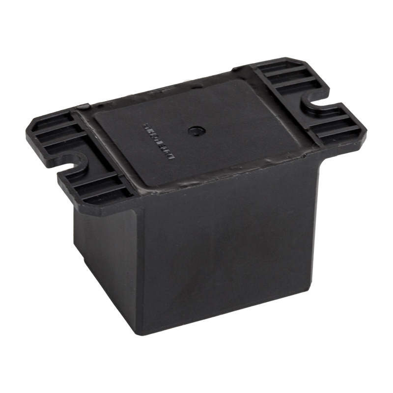 SPDT 5PIN 30A high power relay PCB PIN HLS-T91(16F)-31A:30A240VAC/20A 28VDC 1B:15A 240VAC/10A 28VDC 1C:20A/10A240VAC/28VDCView Product →
Contact material is the second decision. Silver nickel is the general-purpose choice and handles moderate inductive loads well. Silver tin oxide resists welding better under high inrush and is often specified for lamp and motor load. Silver cadmium oxide has excellent arc erosion resistance but is restricted in some markets, which is why many manufacturers now lead with silver tin oxide instead.
Coil power is the third number. Typical PCB-mount power relays for this kind of application consume between 0.36 W and 0.53 W, with some larger types closer to 0.9 W. That difference matters when a monitoring relay is powered from a small auxiliary transformer or from a shared 24 V rail that already carries sensors and displays.
Mechanical and electrical life should be read as two different numbers. A relay with ten million mechanical operations and 100,000 electrical operations at rated load will normally be replaced because of contact wear long before the mechanism fails, which means the electrical life is the number to use when planning maintenance intervals on a machine that cycles frequently.
Size the output contact for the inrush current of the load, not for its steady-state current, and derate the rating for the real cabinet temperature.
A Step-by-Step Selection Walkthrough
The sequence below is the one that works reliably for panel builders and OEM buyers who have to place an order without a full laboratory test programme. Each step produces one line on a specification sheet.
- Define the fault that must be detected. A dry running pump needs undercurrent and phase loss; a machine tool on a weak rural supply needs overvoltage and undervoltage; a generator panel needs frequency and sequence.
- Decide whether the voltage can be measured directly or through a transformer. Most industrial three-phase relays accept line-to-line voltages directly up to roughly 520 V, which covers 400 V and 480 V systems without extra hardware.
- Count the output contacts needed. One changeover contact is enough to drop a contactor; two are needed when an alarm and a trip signal must be independent of each other.
- Choose the reset behaviour. Manual reset with memory is the safer choice wherever an unattended restart could injure someone or damage a process.
- Check the delay range against the process. A compressor needs a longer undervoltage delay than a conveyor because the compressor cannot restart against head pressure.
- Confirm the auxiliary supply available in the panel. A wide-range 110 to 240 V AC/DC supply reduces the number of part numbers a distributor has to stock.
- Calculate the real output load, including contactor coil inrush, and derate for cabinet temperature.
- Verify the mechanical fit. Rail width, terminal pitch and the position of the current transformer terminals all affect how the wiring is dressed.
- Confirm the approvals required in each destination market, and ask for the certificate numbers rather than a claim on a brochure.
- Order samples and test them on the actual supply, ideally during a shift when the plant is at full load, because that is when voltage sag and harmonics appear.
- Agree on the supply terms with the manufacturer: minimum order quantity, lead time, packing format and whether the relay can be supplied under your own part number.
Step ten is the one that is most often skipped under schedule pressure, and it is also the one that pays for itself fastest. A monitoring relay that behaves well on a clean laboratory supply can behave very differently on a plant with a large variable frequency drive running two bays away, and the only way to know is to test it there.
Test the chosen relay on the real supply at full plant load before releasing the specification to production.
Application Scenarios and Typical Settings
Different industries use the same relay families for different reasons, and the settings sheet reflects those reasons. The table below is drawn from the patterns that appear most often in industrial panel design and appliance control boards.
| Application | Functions used | Typical settings | Consequence of a missed fault |
|---|---|---|---|
| Submersible and process pumps | Phase loss, sequence, asymmetry, undercurrent | Undervoltage 0.85 times nominal, 2 s delay | Dry run, impeller damage, motor burnout |
| HVAC and refrigeration | Voltage window, phase sequence, current unbalance | Undervoltage 0.9 times nominal, 3 s delay | Compressor failure and refrigerant loss |
| Machine tool and packaging lines | Overvoltage, undervoltage, phase loss | Window plus or minus 10 percent, 0.5 s delay | Scrap parts, corrupted controller memory |
| Conveyors and material handling | Current monitoring, unbalance | Overcurrent 1.2 times full load, 5 s delay | Jam, belt damage, motor overheating |
| Generator changeover panels | Frequency, voltage window, sequence | Frequency window plus or minus 2 percent | Unstable transfer, equipment damage on switchover |
| Appliance and instrument control boards | Single-phase overvoltage and undervoltage | Fixed window, short delay | Premature failure of electronics and heating elements |
Appliance and instrument manufacturers form a separate purchasing group from industrial panel builders. Their volumes are higher, their unit prices are tighter, and their relays are usually mounted directly on a printed circuit board inside the product rather than in a DIN-rail cabinet. Where a compact board layout is the main constraint, a five pin miniature power relay with a 7 A or 10 A contact rating and PCB pins is often the practical choice.
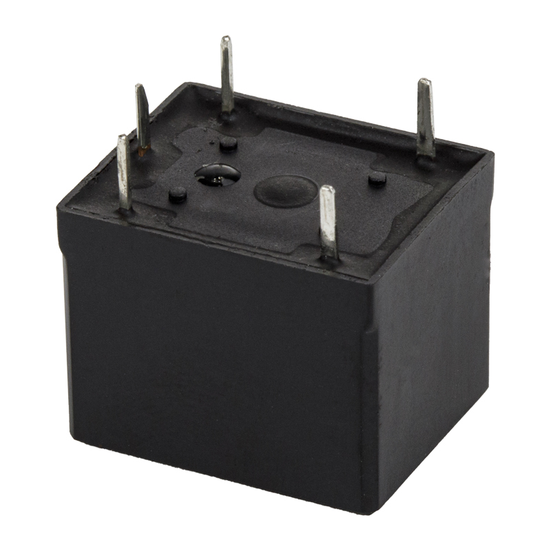 hot selling SPDT 5PIN 7A 10A mini power relay T73 PCB PIN HLS87 A 2 5 0VAC/ 30 VDC 10A 250 VAC/ 30 VDC 15 A 12 0VACView Product →
The current monitoring applications are worth a separate note, because current sensing is where most installation errors occur. A current monitoring relay needs a current transformer on the phase conductor, and the ratio of that transformer must match the setting range of the relay. A 50 to 5 A transformer paired with a relay whose display reads 0 to 5 A will produce sensible numbers only if the primary current is scaled correctly in the setting sheet.
Write the application scenario into the specification, because the same relay model needs completely different settings on a pump and on a conveyor.
How a Power Monitoring Relay Compares with Other Devices
Project specifications frequently confuse monitoring relays with neighbouring products, and the confusion leads to either duplicated hardware or a missing function. The comparison below keeps the roles separate.
| Device | What it watches | Typical output | Best used for |
|---|---|---|---|
| Power monitoring relay | Supply voltage, current, frequency, sequence | Dry contact | Detecting supply quality faults before the load is damaged |
| Thermal overload relay | Motor current and thermal state | Tripping contact | Overload, locked rotor and slow thermal build-up |
| Electronic motor protection relay | Current, thermal model, sometimes voltage | Multiple contacts, communication | Critical motors with detailed diagnostics |
| Contactor | Nothing; it is the switching element | Power contacts | Switching the load itself |
| Voltage transducer | Voltage only | 4 to 20 mA analog | Measurement and trending, not switching |
| PLC with analog inputs | Whatever is wired to it | Programmable outputs | Complex logic, data logging, central control |
The practical rule is that monitoring and protection are complementary rather than alternative. A pump station with both a power monitoring relay and a thermal overload will survive a phase loss that the overload alone would take several minutes to detect, and it will also survive an overload that the monitoring relay alone would never see. Duplicating the two functions inside one multifunction device is a cost decision, not a functional one.
The PLC comparison is the one that comes up most often in modern panel design. A PLC with analog inputs can certainly calculate undervoltage and phase asymmetry in software, and many large installations do exactly that. The argument for keeping a dedicated power monitoring relay is speed and independence. A hardware relay trips in milliseconds without waiting for a scan cycle, keeps working if the PLC program is being edited, and gives the maintenance team a plain-language fault indication instead of a diagnostics screen.
Keep the monitoring function independent of the control program, so that a supply fault is detected even when the controller is offline.
Installation, Wiring and Commissioning Notes
Most field failures of power monitoring relays trace back to installation rather than to the product. The notes below cover the errors that recur most often in maintenance reports.
- Feed the measuring circuit from the load side of the main switch, so the relay sees the same voltage the motor receives.
- Keep measuring conductors away from drive output cables, and cross them at right angles where a crossing is unavoidable.
- Earth the current transformer secondary at one point only, and never leave the secondary open when the primary is energised.
- Use separate auxiliary supply terminals where the model provides them, so a voltage dip on the measuring circuit does not reset the logic.
- Wire the output contact so that loss of auxiliary power also drops the load, unless the process requires the opposite behaviour.
- Leave the setpoint card inside the enclosure after commissioning, and record the date and the responsible engineer.
Commissioning itself should follow a fixed script. Verify the phase sequence before the first start, confirm the display readings against a reference meter, then deliberately create an undervoltage condition with a variable transformer and check that the relay trips at the set threshold and within the set delay. A relay that has never been tested at its threshold is an assumption rather than a protection device.
One additional check is worth the extra ten minutes on any panel with a variable frequency drive: confirm there is no measurable voltage on the measuring terminals when the main switch is open. Capacitive coupling and drive leakage can produce a few volts of stray potential that makes a high-impedance measuring input read values that do not exist.
Prove the trip threshold and the delay on site with a controlled test, because an untested setting is not a protection function.
Maintenance and Troubleshooting
Monitoring relays are among the more reliable components in a control panel, but they are not maintenance free. Contacts wear, settings drift when someone turns a screwdriver in the wrong direction, and current transformers loosen on their terminals. The table below maps the symptoms that technicians report most often onto their usual causes.
| Symptom | Likely cause | Check |
|---|---|---|
| Frequent trips when a nearby motor starts | Trip delay set too short or hysteresis too small | Increase undervoltage delay to 1 to 3 seconds |
| No trip during a known phase loss | Relay measuring on the line side of the switch, or a faulty sensing fuse | Confirm measuring point and fuse continuity |
| Contact does not close when the supply is normal | Latched fault requiring manual reset, or welded contacts | Press reset, then measure contact resistance |
| Reading differs from a reference meter | Harmonic distortion, or a loose measuring terminal | Compare with a true RMS meter at the same point |
| Random restart of a stopped machine | Auto reset enabled where manual reset is required | Change reset mode and update the panel label |
| Contact failure after several years | Electrical life exhausted under inductive load | Replace the unit and consider an interposing relay |
Spare parts planning is straightforward once the failure mode is understood. The measuring electronics rarely fail, so the parts that carry wear are the output relay and, on plug-in designs, the socket. Sockets are the practical answer for installations where the relay has to be swapped during a shift without touching wiring, particularly where an 8 pin or 11 pin plug-in relay is already standard across the plant.
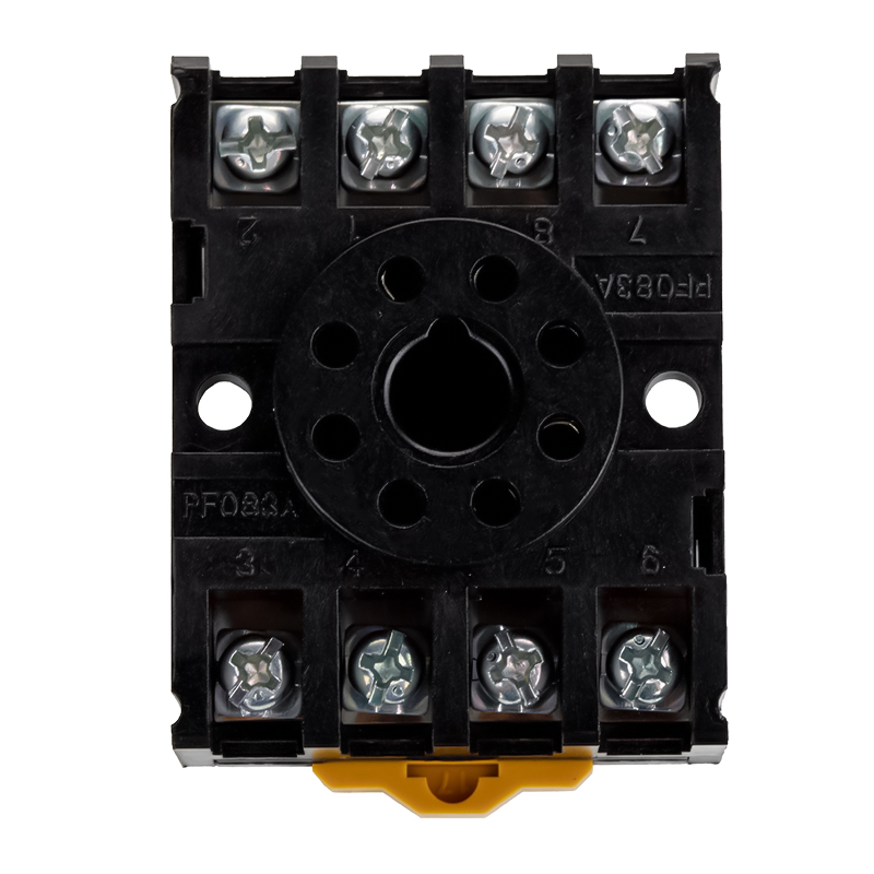 HLS-PF083A relay socket for MK2PNingbo Helishun Electron Co.,Ltd.View Product →
Keeping one spare socket and one spare relay per critical panel is usually cheaper than holding a complete spare drive, and it turns a two hour emergency repair into a two minute swap.
Plan spares around the wearing parts, the output relay and the socket, rather than around the measuring electronics that rarely fail.
Buying Considerations: Manufacturer, Supplier or Wholesaler
Once the technical specification is fixed, the purchasing decision turns on capability rather than features. For a power monitoring relay project, three supplier profiles cover most situations: a component manufacturer that builds the output relay and the socket, a panel-level supplier that assembles complete monitoring devices, and a wholesaler that stocks finished units for immediate delivery.
When evaluating a relay manufacturer, the questions that produce useful answers are about process rather than about price. Ask which quality system is in place and when it was certified, which product certifications are held and under whose name they were issued, what the standard contact materials are, and whether custom coil voltages or contact configurations are possible under an OEM or ODM arrangement. A manufacturer that has held ISO 9001 certification since the early 2000s and carries UL, TUV, CE and CQC marks on its relay ranges is operating at the level most export programmes require.
RoHS compliance should be confirmed in writing rather than assumed from a catalogue statement, because the documentation is frequently requested by European distributors during supplier qualification. Where hazardous area equipment is involved, an IECEx listing may also be relevant, although it applies to a much smaller share of orders than the standard industrial certifications.
For OEM buyers, the practical advantages of working directly with a manufacturer are stable part numbers, the ability to specify coil voltage and contact plating, and a single point of responsibility when a field failure is investigated. For distributors and wholesalers, the advantages are packaging format, carton marking and the availability of a consistent product family across several current ratings so that a single supplier can cover a whole catalogue page.
Production scale and export experience are reasonable proxies for delivery reliability. A plant of several thousand square metres, a workforce above one hundred people, and a sales record covering more than one hundred countries indicate that the supplier has already solved the export documentation, packaging and consistency problems that trip up smaller workshops.
Choose the supplier on certification evidence, production scale and OEM flexibility, then negotiate price against a defined specification.
Frequently Asked Questions About Power Monitoring Relays
What is the difference between a power monitoring relay and a voltage monitoring relay?
A voltage monitoring relay watches voltage only. A power monitoring relay usually watches voltage plus at least one of current, frequency or phase sequence. In practice the terms overlap heavily, and the deciding factor is which measured quantities appear on the datasheet rather than the name printed on the front.
Can a power monitoring relay replace a thermal overload relay?
No. The monitoring relay detects supply faults such as phase loss, undervoltage and asymmetry. It does not model the thermal state of a motor, and it will not detect a mechanical overload that develops slowly at normal voltage. The two devices protect against different failure modes and are normally used together.
Why does my relay trip whenever the neighbouring machine starts?
Because the trip delay is shorter than the duration of the voltage dip caused by the neighbouring start. Increasing the undervoltage delay to one or two seconds, and checking that hysteresis is at least two percent of the setpoint, resolves this in most installations.
Can the output contact drive a contactor coil directly?
Often yes, but only if the contact rating covers the coil inrush current and the cabinet temperature derating. A contact rated 16 A for resistive load may only carry 6 A for an inductive load. Where the margin is thin, an interposing relay with a heavier contact is the safer design.
What is the correct trip delay for phase loss?
Phase loss is normally set fast, typically between 0.1 and 0.5 seconds, because a three-phase motor running on two phases draws a rapidly rising current. There is rarely a process reason to delay this function.
Do I need a current transformer?
Only for the current monitoring functions. Voltage monitoring is normally connected directly. If current monitoring is required, the transformer ratio must match the setting range of the relay so the displayed values correspond to the actual primary current.
Which approvals should I request before placing an order?
UL and CQC for North America and China, TUV and CE for Europe, and RoHS for hazardous substance compliance across the European Union. Ask for certificate numbers and the certified model list, not just a claim printed in a brochure.
Should I choose auto reset or manual reset?
Manual reset with memory is the safer choice wherever an unattended restart could injure an operator or damage a process. Auto reset is acceptable on small standalone machines where the fault clears itself and restarting immediately is normal.
Can the same relay be used on a single-phase supply?
Some three-phase models accept single-phase connection with the unused voltage terminals linked, but not all do. Where the application is known to be single-phase, a dedicated single-phase voltage monitoring relay is simpler to specify and to commission.
How do I test a monitoring relay after installation?
Use a variable transformer to drive the voltage below the set threshold and confirm the trip point and the delay with a stopwatch. Then confirm the contact actually drops the contactor. A relay that has never been tested at its threshold has not been verified.
Most questions about power monitoring relays resolve into two decisions: which fault must be caught, and how long the relay is allowed to wait before acting on it.
Continue Reading on This Site
The background behind the relay ranges discussed here, including the factory profile, certifications and OEM cooperation policy, is summarised on the company pages. Readers who want to go deeper into the engineering side of relay selection will find the selection principle article useful alongside this guide.
Start with the fault you need to catch, size the output contact for the real load, and verify both on the actual supply before the panel leaves the workshop.


