



 English
 中文简体
中文简体Content
- 1 What a Relay for Motor Protection Does
- 2 Core Protection Functions You Should Specify
- 3 How to Select a Relay for Motor Protection
- 4 Wiring and Installation Practices
- 5 Maintenance and Troubleshooting
- 6 Sourcing from a Relay Manufacturer, Supplier, and Wholesaler
- 7 FAQ About Relay for Motor Protection
- 7.1 Can a general power relay be used as a relay for motor protection?
- 7.2 What trip class should I choose for a pump motor?
- 7.3 Why does the relay trip during start-up even though the motor runs fine?
- 7.4 How do I set the overload current on a relay for motor protection?
- 7.5 What certifications should a motor protection relay have?
- 8 Final Selection Checklist
A 7.5 kW pump motor trips after 20 minutes of normal running, then restarts and trips again. The maintenance team checks the contactor, tightens the terminals, and replaces the overload heater. The tripping continues. The real problem is often not the motor itself, but the relay for motor protection that is set too close to the running current or is missing phase-failure logic. In motor circuits, the protection relay is the decision point between a nuisance trip and a burned winding.
The practical answer is straightforward: choose a relay for motor protection that matches the motor’s full-load current, trip class, and starting profile, then verify the wiring, reset mode, and environmental rating before installation. A relay that is undersized will nuisance trip; one that is oversized may never protect the winding during a locked-rotor event. The sections below explain what the relay does, how to select it, how to wire it, and what to confirm with a relay manufacturer or supplier.
Key takeaway: The relay for motor protection must be selected against the motor’s actual full-load current and starting duty, not just the nameplate kW rating.
What a Relay for Motor Protection Does
A relay for motor protection monitors one or more operating conditions and disconnects the motor control circuit when those conditions move outside safe limits. In a basic thermal overload relay, the sensing element is a bimetal strip heated by motor current. In a more complete motor protection relay, current transformers, voltage inputs, and temperature sensors feed a measuring circuit that evaluates overload, phase loss, phase sequence, stall, underload, and ground fault.
The difference matters at commissioning. A thermal overload relay protects against sustained overcurrent, but it cannot detect a missing phase on a lightly loaded motor, and it cannot distinguish a reverse phase rotation from a normal start. A dedicated motor protection relay can block a start until the phase sequence is correct, which protects pumps, compressors, and fans from running backward.
| Relay type | Primary protection | Typical use | Limitation |
|---|---|---|---|
| Thermal overload relay | Overload, some phase imbalance | Small pumps, fans, conveyors | No phase sequence or ground fault |
| Electronic motor protection relay | Overload, phase loss, phase sequence, stall, underload, ground fault | Process pumps, compressors, mixers | Higher cost, needs correct CT ratio |
| General power relay | Load switching, control logic | Control panels, appliance motors | Not a standalone protection device |
In many control panels, a general power relay or contactor handles the switching duty while a separate protection relay watches the motor. The two functions are related but not interchangeable. The protection relay must have a contact rating and thermal capacity that can carry the motor current without welding, and its trip curve must coordinate with the contactor and upstream breaker.
Key takeaway: A relay for motor protection is a measuring and decision device; the contactor or power relay is the switching device. Do not ask one component to do both jobs unless it is specifically rated for the duty.
Core Protection Functions You Should Specify
Motor protection relays are specified by the functions they include, not only by their current range. For a supplier quotation or a replacement selection, list the functions that the application actually needs. The following are the most common functions in motor protection relays.
- Overload protection: A timed trip when current exceeds the set value. Trip class 10 is common for standard motors; class 20 or 30 is used for high-inertia loads with long starting times.
- Phase loss and imbalance: Detection of a missing phase or severe current imbalance, which can overheat a three-phase motor even when the average current looks normal.
- Phase sequence: Prevention of reverse rotation. This is critical for pumps, compressors, and screw conveyors where reverse rotation can damage the driven equipment.
- Locked rotor and stall: A fast trip when the motor draws starting current but does not accelerate, or when current remains high after the start window.
- Underload or dry-run: Detection of a sudden drop in current, often used on submersible pumps and screw feeders to prevent dry running.
- Ground fault: Detection of leakage current to earth, usually through a core-balance current transformer or a residual connection.
- Temperature input: PTC or NTC thermistor input for direct winding temperature monitoring on motors that have embedded sensors.
Not every motor circuit needs every function. A small fan motor may need only overload and phase loss. A 30 kW process pump may justify phase sequence, ground fault, and thermistor input. The selection risk is asymmetric: adding a function that is not needed increases cost and wiring complexity, but omitting phase sequence or ground fault can leave a failure mode completely unprotected.
Key takeaway: Specify protection functions from the motor’s failure modes and starting duty, not from the relay’s feature list. Phase loss and phase sequence are the two functions most often missed in replacement projects.
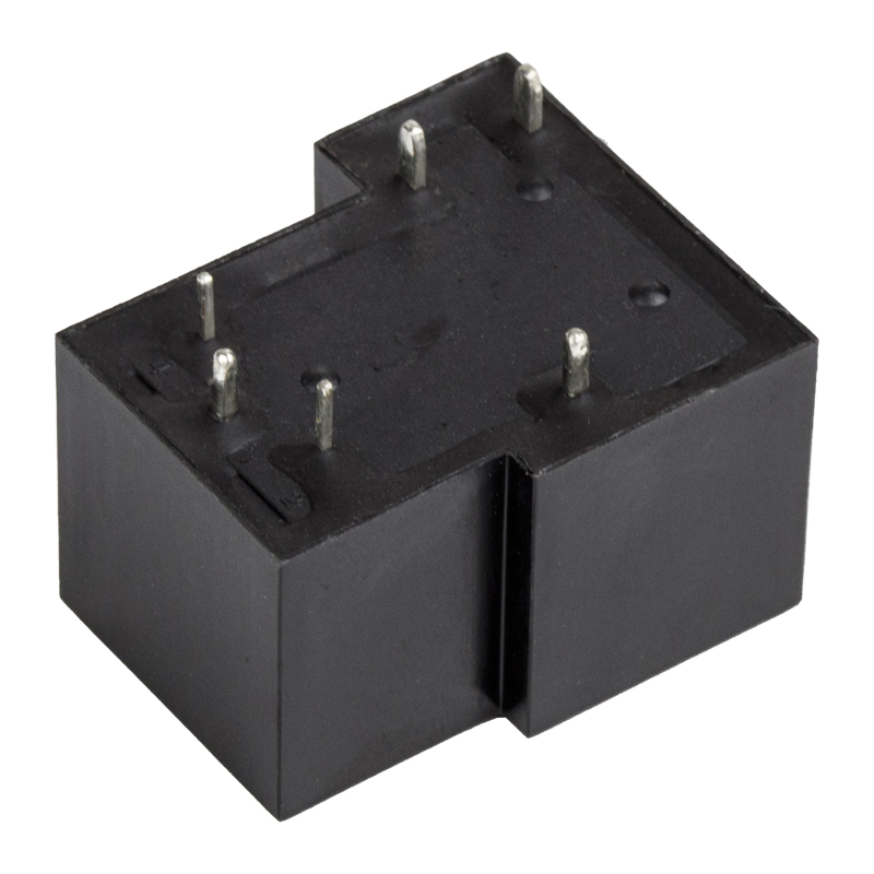 hot selling SPDT 5PIN 6PIN 30A high power relay T90 PCB PIN HLS-T90(15F)Max Switching VoltageView Product →
How to Select a Relay for Motor Protection
Start with the motor’s full-load current, not the kW rating. Nameplate current is the basis for the relay setting range. Then check the starting current and starting time. A motor that draws 6 times full-load current for 8 seconds needs a trip class and time delay that allow the start to complete without tripping, yet still protect the winding if the rotor locks.
The chart below shows typical full-load currents for common three-phase motor sizes and the relay contact rating that should be considered. It is a starting point for discussion, not a substitute for the actual nameplate current and application data.
Typical Full-Load Current and Suggested Relay Contact Rating
The chart suggests that relay contact rating should generally be at least one frame size above the motor full-load current when the relay also carries starting current. A 7.5 kW motor with 15.5 A full-load current may draw 90 A or more during a direct-on-line start, so the relay or contactor must be rated for that transient duty. The setting range, however, should be centered on the full-load current, not the starting current. If the relay is set at the starting current, it will not protect the motor during a moderate overload. If it is set too low, nuisance trips will follow.
After current and trip class, check the reset mode. Manual reset is common for operators who must inspect the motor before restart. Automatic reset is used in unattended pump stations, but it can be dangerous on a jammed conveyor because it may restart into a fault. Also confirm the relay’s rated insulation voltage, impulse withstand, and terminal capacity. For replacement projects, the pin layout, mounting footprint, and terminal numbering often matter as much as the electrical rating. A useful reference for replacement logic is the relay selection principle used by panel builders.
Key takeaway: Select the relay for motor protection by full-load current, trip class, starting time, and reset mode. Contact rating must cover starting current; the trip setting must center on full-load current.
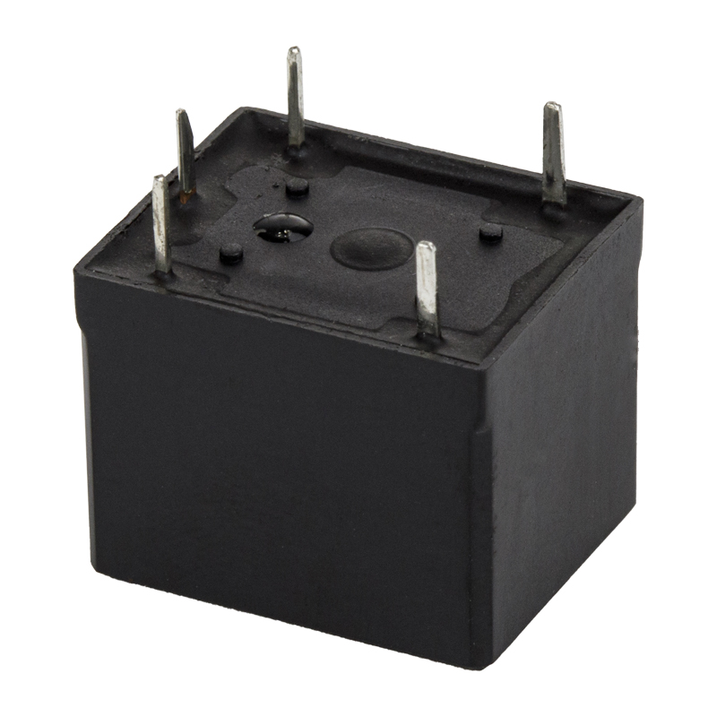 hot selling SPDT 5PIN 7A 10A mini power relay T73 PCB PIN HLS87 A 2 5 0VAC/ 30 VDC 10A 250 VAC/ 30 VDC 15 A 12 0VACView Product →
Wiring and Installation Practices
Most motor protection problems appear after installation, not before. The current transformers must be installed in the correct direction, with the secondary wiring shorted before the relay is connected. An open CT secondary can generate dangerously high voltage. The phase sequence must be checked with a meter, not assumed from cable color. The relay’s control supply should be taken from the same phase set as the motor, or from a dedicated control transformer, depending on the relay design.
Terminal torque is another common issue. A loose terminal on a current path heats up, increases resistance, and can cause a false overload trip. Use the manufacturer’s torque specification and re-check after the first week of operation. Keep the relay away from contactor arc chutes and VFD output cables. High-frequency noise from a variable-frequency drive can interfere with electronic protection relays unless the relay is specifically shielded or the wiring is segregated.
For small motor circuits, a compact power relay such as a T73 PCB relay can handle the control switching while a separate overload relay protects the winding. In larger panels, the protection relay is often mounted on a DIN rail with a separate contactor. Whichever arrangement is used, leave space for a current injection test. Being able to inject a known current and verify the trip time is the only reliable way to confirm the relay is set correctly after wiring.
Key takeaway: Correct CT direction, phase sequence, terminal torque, and noise separation prevent most false trips. Always verify the final setting with a current injection test.
Maintenance and Troubleshooting
A motor protection relay should be tested at least once a year in critical processes, and after any event that caused a trip. Start by recording the trip current, trip time, and the relay’s event log if it has one. Compare the recorded current with the normal running current. A gradual increase in running current may indicate mechanical wear, a failing bearing, or a partially blocked impeller. A sudden high current with a short trip time usually points to a locked rotor or a short circuit downstream.
Check the relay’s environment. Dust, humidity, corrosive gas, and high ambient temperature all affect electronic relays. The storage and operating temperature ranges matter, especially in outdoor cabinets. If the relay has a display, confirm that the displayed current matches a clamp meter reading. A mismatch usually means the CT ratio setting is wrong or one phase is not being measured. For common fault patterns, the site’s guide to relay common problems and handling measures is a useful troubleshooting reference.
Key takeaway: Trend the running current and verify displayed current against a clamp meter. Most nuisance trips are caused by settings, CT ratios, or terminal resistance, not by the relay itself.
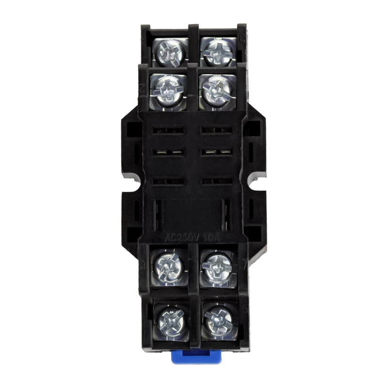 HLS-PTF08A-01 relay socket for 13F-1 or 13F-2Ningbo Helishun Electron Co.,Ltd.View Product →
Sourcing from a Relay Manufacturer, Supplier, and Wholesaler
For OEM projects, the relay is often part of a control board, a pump controller, or a panel assembly. The sourcing decision then involves more than unit price. A relay manufacturer that also supplies matching sockets, publishes UL and TUV certificates, and maintains consistent pin layouts can reduce integration risk. Ningbo Helishun Electron Co., Ltd., for example, has manufactured relays since 2000, operates an 8,800 square meter facility in Ningbo, and holds UL, TUV, CE, CQC, RoHS, and ISO 9001 approvals. Its product range includes general power relays, automotive relays, telecom relays, and relay sockets, with current ratings from 2 A to 80 A.
When evaluating a relay supplier or wholesaler, ask for the following: the specific certificate file numbers, the contact rating under AC-3 or DC-1 duty, the expected electrical life at the application current, and the terminal material and plating. For motor protection circuits, also confirm the relay’s ability to withstand inrush current and its performance after 10,000 operations at rated load. A supplier that can provide test data, not only a datasheet, is usually better prepared for OEM qualification.
For distributors and panel builders, compatibility is a practical advantage. If the relay footprint and socket match an existing installation, replacement and field service become easier. That is why many buyers look for a manufacturer that offers both the relay and the socket as a set, and that can support OEM or ODM customization for coil voltage, contact form, and terminal arrangement. You can review the company’s background and certifications on the about page before requesting samples or a quotation.
Key takeaway: Source motor protection relays from a manufacturer that can supply matching sockets, verified certifications, and OEM/ODM support. Compatibility reduces field service risk.
FAQ About Relay for Motor Protection
Can a general power relay be used as a relay for motor protection?
A general power relay can switch the motor control circuit, but it does not measure current or provide a trip curve. It should be paired with a dedicated overload or motor protection relay. Using a power relay alone leaves the motor without overload protection.
What trip class should I choose for a pump motor?
Most standard pumps use trip class 10. If the pump has a high-inertia load or a long starting time, class 20 may be needed. The correct choice depends on the measured starting time and the motor manufacturer’s recommendation.
Why does the relay trip during start-up even though the motor runs fine?
The most common causes are a trip class that is too fast for the starting time, a current setting that is too close to the starting current, or a CT installed on the wrong phase. Verify the starting current with a recorder and compare it with the relay’s trip curve.
How do I set the overload current on a relay for motor protection?
Set the relay to the motor’s nameplate full-load current. If the motor runs in a high ambient temperature or has a service factor, consult the motor datasheet. Do not set the relay to the starting current or to the next standard size up without verifying the winding temperature rise.
What certifications should a motor protection relay have?
For industrial use, UL, TUV, CE, and CQC are common. RoHS matters for many markets. The exact requirement depends on the panel’s destination and the end customer’s specification. Always request the certificate file number and confirm it covers the specific model.
Key takeaway: The most frequent relay for motor protection problems are wrong trip class, incorrect current setting, and CT installation errors. Confirm all three before replacing the relay.
Final Selection Checklist
Before ordering a relay for motor protection, confirm the motor full-load current, starting current, and starting time. Choose the trip class and reset mode. Verify the relay’s contact rating under the actual starting duty. Check the phase sequence, ground fault, and temperature inputs required by the application. Confirm the CT ratio, terminal layout, and mounting compatibility. Finally, ask the supplier for certificates, test data, and socket availability. A relay that passes these checks will protect the motor without creating a maintenance burden.
Key takeaway: Match the relay for motor protection to the motor’s full-load current, starting duty, and failure modes, then verify installation with a current injection test.


