



 English
 中文简体
中文简体Content
- 1 Why Test Relays with a Voltmeter?
- 2 How to Test Relays with a Voltmeter: Step-by-Step Process
- 3 The Three Measurements Behind Every Relay Test
- 4 Typical Coil Resistance Readings for Common 12 V Relay Families
- 5 Understanding Relay Contact Measurements and Voltage Drop
- 6 Common Relay Faults You Can Diagnose with a Voltmeter
- 7 Testing Different Relay Families: Automotive, Power, and Telecom
- 8 Routine Relay Checks and Choosing a Replacement
- 9 Relay Testing with a Voltmeter: FAQ
- 9.1 Q: Do I need a special voltmeter to test a relay?
- 9.2 Q: How do I test relays with a voltmeter when the relay is still installed in the circuit?
- 9.3 Q: What resistance should a relay coil read?
- 9.4 Q: Why does my relay click but the load stays off?
- 9.5 Q: What does a voltage drop of 0.4 V across a closed contact mean?
- 9.6 Q: Can a bad relay socket make the relay test good but the circuit fail?
- 9.7 Q: Can I test a solid-state relay this way?
- 9.8 Q: How often should I test relays in industrial equipment?
- 10 Related Resources for Relay Testing and Selection
Why Test Relays with a Voltmeter?
A fuel pump relay clicks, yet the pump stays silent. A heating contactor pulls in, but the oven never warms. An industrial control relay energizes on the panel, but the motor that follows it does not spin. In each of these situations, the fastest way to separate a bad relay from a bad circuit is the same: reach for a voltmeter. This guide explains how to test relays with a voltmeter in five repeatable steps, what readings to expect, and how to tell whether the problem is in the coil, the contacts, the socket, or the surrounding wiring.
The short answer is that a digital multimeter with resistance and voltage modes contains everything you need for a complete relay check. In resistance mode it verifies the coil and the contact paths; in voltage mode it proves that the relay can carry its working current without excessive loss. A relay that passes all three checks, coil continuity, contact switching, and contact voltage drop, is almost certainly serviceable. A relay that fails any one of them should be taken out of service without debate, because no amount of circuit troubleshooting will fix a component that cannot perform its basic job.
Understanding why the test works is just as useful as the procedure itself. An electromagnetic relay is built around a coil that generates a magnetic field when energized, a movable armature that responds to that field, and one or more contact sets that open or close the load circuit. The coil is an inductor wound from copper wire, so it has a measurable DC resistance. The contacts are mechanical interfaces whose resistance is normally only a few milliohms but rises as they arc, oxidize, and wear. A voltmeter can see both of these physical changes, which is exactly why it is the right tool for relay diagnosis.
Because the same construction appears in automotive relays, general-purpose power relays, and telecom relays, the method described here applies across all of them. Only the pin numbering, coil voltage, and typical coil resistance change from one family to the next. Once you can test one relay correctly, you can test any electromechanical relay you will meet in a vehicle, a control cabinet, or a printed circuit board.
Key conclusion: A three-part voltmeter test, coil continuity, contact switching, and voltage drop under load, tells you with high confidence whether a relay is good or bad, and it takes about five minutes.
How to Test Relays with a Voltmeter: Step-by-Step Process
Before you begin, gather a few basic items: a digital or analog voltmeter with resistance and DC voltage ranges, a 12 V battery or a bench power supply, two short jumper wires, a load such as a 12 V headlamp bulb or a power resistor, and the relay data sheet or pin diagram. These steps assume you are working on a standard automotive or general-purpose relay with a 12 V DC coil; for 24 V or 5 V coils, simply adjust the supply voltage to the rated coil voltage.
Step 1: Identify the Relay Terminals
Every relay test starts with knowing which pins do what. Most relays have a small diagram printed on the top of the case, and the same diagram appears in the data sheet. On automotive relays, the coil is almost always on pins 85 and 86, pin 30 is the common contact, pin 87 is the normally open contact, and pin 87a is the normally closed contact on five-pin versions. A four-pin automotive relay has only 85, 86, 30, and 87.
General-purpose power relays use a variety of layouts. Socket mount relays in the 8-pin, 11-pin, and 14-pin families label the coil as pins A1 and A2 or as two numbered pins at one end of the base, while the contact pairs are printed beside each terminal. PCB relays such as the T73 or T90 series have a small schematic printed on the dust cover. If the marking is unreadable, search the part number printed on the relay case; if that fails, you can find the coil pins with the voltmeter itself, because the coil is usually the only pin pair that reads a finite resistance of tens to hundreds of ohms.
Step 2: Test the Coil Resistance
Set the meter to the lowest resistance range, usually 200 ohm or 2 kohm, and place one probe on each coil pin. The reading should be close to the value printed on the relay or listed in the data sheet, typically 60 to 120 ohm for a 12 V automotive relay and 100 to 200 ohm for a small 12 V power relay. A reading of open loop means the coil wire has burned through and the relay is dead. A reading of essentially 0 ohm means the winding is shorted and the relay should also be replaced.
One caution: some relays include a suppression diode or resistor wired across the coil to protect the driving circuit from voltage spikes. If the relay has this internal component, the coil resistance reading can look unusually low or even polarity dependent. Check the data sheet first. When in doubt, compare the reading between the two probe directions; a diode gives a low reading in one direction and a high reading in the other, while a plain coil reads the same both ways.
Step 3: Test the Contact Paths
With the coil still de-energized, measure across the normally closed contacts. On a five-pin automotive relay, measure between 30 and 87a; the meter should show near 0 ohm. Then measure across the normally open contacts, between 30 and 87; the meter should show open loop, because these contacts should be separated with the coil off.
Now energize the coil by connecting the coil pins to the correct DC supply voltage. You should hear a distinct click as the armature moves. Repeat the contact measurements while the coil is held energized: the normally open path between 30 and 87 should now read near 0 ohm, and the normally closed path between 30 and 87a should read open loop. If the contacts do not change state, the armature is stuck, the contacts are welded, or the coil is too weak to overcome spring pressure. Any of these conditions means replacement.
Step 4: Check the Voltage Drop Under Load
Resistance readings prove that a contact path is connected, but they do not prove the contact can carry current efficiently. A pitted or oxidized contact can pass only milliamps while showing a convincing near zero reading in ohms mode. The voltmeter answers this question in voltage mode: with the relay energized and a real load connected through the contacts, place the probes directly across the closed contact pair and measure the voltage while the load is running.
On a 12 V circuit with a load current of 5 to 40 A, a healthy contact set shows less than 0.1 V across it. A reading between 0.1 and 0.5 V indicates a contact that is worn or contaminated and should be planned for replacement. A reading above 0.5 V, or a reading close to the full supply voltage, means the contact is effectively open and the relay must be replaced immediately. The beauty of this test is that it catches exactly the failures that resistance mode misses.
Step 5: Verify the Control Circuit
If the relay tests good on the bench but the circuit still does not work, the fault may be upstream or downstream of the relay. Reinstall the relay, energize the circuit normally, and measure the voltage across the coil terminals while the control switch is on. If the coil receives its rated voltage but the relay does not click, the relay is faulty despite passing the bench test. If the coil receives no voltage, the problem is in the switch, the wiring, the ground path, or the control module, not in the relay itself.
This control-side check matters more than many technicians realize. A relay can be perfectly functional and still be blamed for a failure caused by a corroded connector, a blown fuse, or a failing sensor that never sends the coil its operating voltage. Measuring at the coil terminals separates these two worlds cleanly.
Bench Test versus In-Circuit Test
Bench testing, with the relay removed, and in-circuit testing, with the relay installed, answer different questions. The table below summarizes the difference so you can choose the right approach.
| Bench test (relay removed) | In-circuit test (relay installed) |
| Uses resistance (ohm) mode for both coil and contacts. | Uses voltage (V) mode only, never resistance on a live circuit. |
| Gives the most accurate, isolated readings. | Fastest way to verify coil supply and contact drop in the real circuit. |
| Requires a battery or bench supply to energize the coil. | Uses the circuit's own control signal to energize the coil. |
| Best for a precise pass or fail decision on the relay itself. | Best for finding wiring, switch, sensor, or module faults upstream. |
| No risk of backfeeding adjacent circuits. | Parallel paths can create misleading resistance readings, so stay in voltage mode. |
Key conclusion: Use the bench test for a definitive relay verdict, then use the in-circuit voltage test to confirm the rest of the control loop is actually delivering power to the coil.
The Three Measurements Behind Every Relay Test
Every complete relay test, no matter how elaborate the procedure looks, reduces to three measurements. The first is coil continuity, which confirms the electromagnetic side of the relay is intact. The second is contact state, which confirms the mechanical contacts open and close in the proper sequence. The third is contact voltage drop, which confirms the closed contacts can carry their rated load without generating excessive heat or voltage loss. If you understand these three measurements, you can diagnose a relay failure in any brand, any voltage, and any package style.
The table below maps each measurement to the meter mode, the expected reading, and the interpretation. Keep this table in mind when you are working on an unfamiliar relay; it converts confusing numbers into a simple verdict.
| Measurement | Meter mode | Expected reading | Interpretation |
|---|---|---|---|
| Coil continuity | Resistance (ohm) | Specified coil value, typically 60 to 200 ohm for 12 V relays | Open loop means a burned coil; near zero means a shorted coil |
| NO contacts, coil off | Resistance (ohm) | Open loop | A low reading means the contacts are welded or stuck closed |
| NC contacts, coil off | Resistance (ohm) | Near 0 ohm | A high or open reading means the NC path is broken |
| NO contacts, coil energized | Resistance (ohm) | Near 0 ohm on a good relay | High resistance means pitting, oxidation, or weak contact pressure |
| Contact voltage drop | Volts (V) | Below 0.1 V at rated load current | Higher values indicate excessive contact resistance |
Notice that the expected values are ranges, not fixed numbers. A relay manufacturer designs each model for a specific coil voltage, coil power budget, and contact rating, so a 10 A relay and a 40 A relay naturally read differently. What never changes is the logic: compare the measured value with the specification, then judge whether the interpretation falls into the healthy, marginal, or failed column.
Key conclusion: Coil continuity, contact switching, and voltage drop are the three pillars of relay testing; no relay should be cleared for service until all three have been verified.
Typical Coil Resistance Readings for Common 12 V Relay Families
Coil resistance is the easiest relay measurement to take, and it is also the one most often misinterpreted. Different relay families are designed for different coil power budgets, so their resistance values can differ by a factor of ten or more. An automotive relay in a 12 V system typically draws 100 to 200 mA of coil current, which corresponds to a low resistance of roughly 60 to 120 ohm. A telecom relay, by contrast, is built for low-power logic drive and may measure 400 to 800 ohm on the same 12 V coil. The chart below shows representative DC coil resistance values for common 12 V relay families, so you can quickly judge whether a reading is plausible for the type of relay on your bench.
Representative DC coil resistance of common 12 V relay families (measured across coil terminals)
The clearest pattern in this chart is the separation between power relays and telecom relays. Automotive and general-purpose relays sit in the low-resistance range because they must pull in a heavy armature and compress strong contact springs. Telecom relays handle tiny signal currents, so their springs are light and the coil can be wound with thousands of turns of very fine wire. More turns mean a higher DC resistance for the same nominal coil voltage, which is why telecom coils often read several hundred ohm. When you test a relay, always compare the measured coil value with the value marked on the relay or listed in its data sheet. A reading within about 20 percent of the specified value is normal and acceptable. A reading far below the specified value suggests a partial short inside the winding, even if the relay still clicks. An open loop reading means the coil wire has burned through, usually from overvoltage, a faulty coil suppression component, or the natural end of its life. Coil resistance is a static measurement and says nothing about the contacts, which are the parts that actually carry the load current. That is why a good coil reading should never be treated as proof that the relay is serviceable. You must still verify contact switching and voltage drop before putting the relay back into service. Treat the coil check as the first gate in a three-step test, not as the whole test.
Key conclusion: A coil reading that matches the data sheet proves only that the electromagnet is intact; the contacts still deserve the same attention as the coil before the relay is trusted with a real load.
Understanding Relay Contact Measurements and Voltage Drop
Contacts are the part of the relay that does the real work, and they are also the part that wears fastest. Every time a relay opens or closes under load, a small arc forms between the contact surfaces. Over thousands of cycles this arc erodes the contact material, leaves carbon and oxide deposits, and gradually increases the contact resistance. A new relay contact may measure 5 to 10 milliohm; a worn contact can measure 50 milliohm or more. That change is tiny in absolute terms, but at a load current of 20 A, 50 milliohm generates a voltage drop of 1 V and more than 20 W of heat inside the relay case.
This is exactly why resistance mode alone is not enough. The ohmmeter in a handheld multimeter cannot reliably resolve a difference between 8 milliohm and 40 milliohm, because the test leads themselves add about 0.1 to 0.2 ohm. The voltage drop test converts a very small resistance difference into a much larger and more readable voltage difference. With the load current flowing, a healthy contact shows almost no voltage across it, while a degraded contact shows a voltage proportional to its resistance and the current. The table below gives practical thresholds for a 12 V relay rated 10 to 40 A.
| Condition | Voltage drop across contact | Approximate contact resistance | Typical cause | Action |
|---|---|---|---|---|
| Healthy | Below 0.1 V | Below 10 milliohm | Normal switching wear | Continue service |
| Marginal | 0.1 to 0.5 V | 10 to 50 milliohm | Oxidation, light pitting, contamination | Plan replacement |
| Failed | Above 0.5 V or full supply voltage | Above 50 milliohm or open | Heavy arcing, welding, severe contamination | Replace immediately |
These thresholds are conservative and work well for most general-purpose and automotive relays. For a very high current relay, such as an 80 A automotive unit, even 0.2 V of drop wastes 16 W and can overheat the terminals, so the acceptable window is tighter. For a low-current telecom relay, the absolute voltage drop is much smaller because the current is only a few amps, so a reading of 0.2 V under a 2 A signal load is more alarming than the same reading on a 10 A power relay.
One more reason to use the voltage drop test is that it sees the whole contact path, including the junction between the relay terminal and the socket blade. A loose socket can produce the same symptoms as worn contacts. If you measure a high voltage drop across the contact but the relay itself tests clean on the bench, inspect the socket terminals, because the resistance you found may live in the connection rather than in the relay.
Key conclusion: The voltage drop test is the single most informative measurement a voltmeter can take on a relay, because it reveals the real resistance of the entire contact path at working current.
Common Relay Faults You Can Diagnose with a Voltmeter
Most relay failures fall into a small set of patterns, and each pattern produces a recognizable reading on the voltmeter. Once you learn these patterns, you can diagnose a failed relay in seconds instead of swapping parts blindly. The table below lists the six most common faults, the measurement that exposes each one, and the action you should take.
| Fault | Measurement | Reading | Likely cause | Action |
|---|---|---|---|---|
| Open coil | Resistance across coil pins | Open loop | Coil burnout from overvoltage or end of life | Replace relay |
| Shorted coil | Resistance across coil pins | Near 0 ohm or far below spec | Insulation breakdown inside the winding | Replace relay |
| Welded contacts | Resistance across NO contacts with coil off | Near 0 ohm | Arcing from inrush current or a shorted load | Replace relay and inspect the load |
| High contact resistance | Voltage drop across closed contacts under load | Above 0.5 V on a 12 V circuit | Pitting, oxidation, weak contact pressure | Replace relay |
| Intermittent contact | Resistance across closed contacts while tapping the relay | Fluctuates between 0 ohm and open loop | Worn contact wiper or loose internal connection | Replace relay and inspect the socket |
| Coil-to-contact leakage | Resistance between coil pins and contact pins | Any reading below open loop | Insulation failure, moisture ingress, carbon tracking | Replace relay immediately |
The intermittent contact case deserves special mention because it is the easiest to miss. A relay can read perfectly when it is cold and sitting on the bench, then fail once it warms up or vibrates in service. If you suspect an intermittent relay, energize the coil, monitor the resistance across the closed contacts, and tap the relay case gently with a screwdriver handle. A reading that jumps from near zero to open loop as you tap is a relay that can drop its load at any moment, and it belongs in the trash, not back in the machine.
Also remember that a welded contact is often a symptom, not the root cause. If the contacts weld, the load circuit probably experienced a large inrush or a short circuit. Replacing the relay without checking the load invites a repeat failure. Measure the load resistance separately and look for grounded wiring before you install the new relay.
Key conclusion: Six fault patterns, open coil, shorted coil, welded contacts, high contact resistance, intermittent contact, and coil leakage, cover nearly every relay failure, and a voltmeter can identify all six.
Testing Different Relay Families: Automotive, Power, and Telecom
The testing procedure remains the same for every electromechanical relay, but each major relay family has small practical differences in pinout, coil voltage, and load type. The notes below help you apply the step-by-step method without guessing.
Automotive relays
Automotive relays are built to switch headlamps, fuel pumps, cooling fans, horns, and other vehicle loads at 12 V or 24 V. Four-pin versions contain the coil plus one normally open contact; five-pin versions add a normally closed contact. When testing an automotive relay, use a 12 V battery or a bench supply, and use a headlamp bulb as the load for the voltage drop test. A healthy relay should show well under 0.1 V across the closed contacts at the bulb current.
Some automotive relays include a suppression diode or resistor across the coil, so check the data sheet before judging a coil reading. If the relay has failed and the footprint is a standard ISO terminal layout, a replacement 5-pin 40 A automotive relay with a standard ISO footprint is usually a direct swap that restores the circuit without rewiring. Always confirm the coil voltage matches the vehicle system before installing.
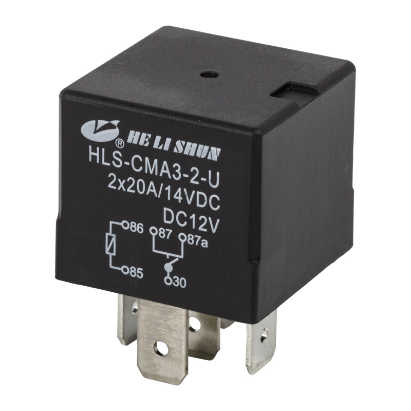 Custom hot selling 5PIN 40A automotive relay PCB QUICK PIN HLS-CMA3 Suppliers, OHelishun Electron Co.,Ltd is China Custom hot selling 5PIN 40A automotive relay PCB QUICK PIN HLS-CMA3 Suppliers and OEM Factory, CONTACT...View Product →
General-purpose power relays
General-purpose relays cover a wide range of industrial and appliance duty, from the small 5-pin PCB relays such as the T73 and T90 series to the socket-mounted 8-pin, 11-pin, and 14-pin relays used in control cabinets. These relays switch heaters, motors, lighting, and solenoids at voltages from 5 V DC to 240 V AC, and their coil voltages can be AC or DC. When testing a socket-mounted relay, you can probe the socket terminals directly, which is a practical advantage because it also tests the wiring down to the socket.
For PCB-mounted circuits, a T73 mini power relay is a common form factor in appliance control boards and small machines; before replacing one, verify the pin spacing, coil voltage, and contact rating against the original relay. The voltage drop test is especially important in this family because power relay contacts that switch motors and heaters are exposed to repeated inrush currents that accelerate contact wear.
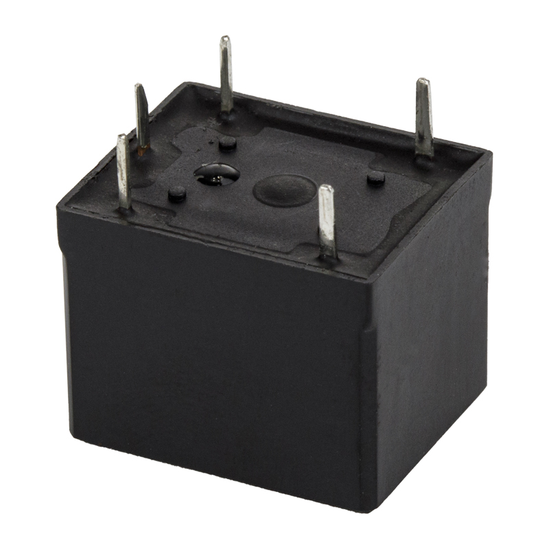 Custom mini power relay T73 PCB Relay Suppliers, FactoryHelishun Electron Co.,Ltd is China Custom hot selling SPDT 5PIN 7A 10A mini power relay T73 PCB PIN HLS8 Suppliers and OEM Factory, CONT...View Product →
Relay sockets and wiring
A relay socket is not a passive lump of plastic; it is part of the current path and a frequent hidden cause of field failures. Loose socket terminals, oxidation, and carbon tracking on the socket surface all produce the same symptoms as a bad relay: the load drops out, the relay feels warm, and everything tests fine when the relay is removed. When a socket-mounted relay fails the voltage drop test, repeat the measurement across the socket terminals with the relay plugged in. If the socket itself shows the drop, replace the socket as well as the relay.
On an 8-pin octal-style panel, a matching MK2P relay socket restores full contact pressure and eliminates a common source of intermittent operation. Socket-mounted relays are preferred in plants precisely because the socket keeps the relay replaceable without touching the wiring, but that convenience only works when the socket is maintained with the same care as the relay.
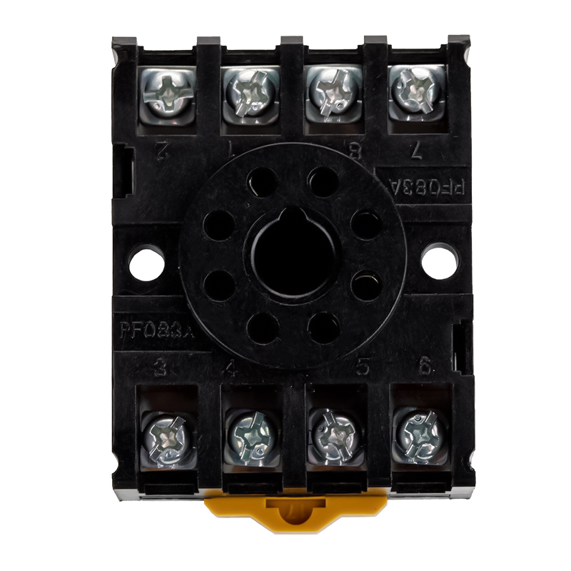 Custom HLS-PF083A relay socket for MK2P Suppliers, OEM Factory - Ningbo HelishunHelishun Electron Co.,Ltd is China Custom HLS-PF083A relay socket for MK2P Suppliers and OEM Factory,View Product →
Telecom relays
Telecom relays operate at signal levels of a few volts and a few amps, and they are common in communication equipment, alarm panels, and control logic. Their coils typically have a much higher resistance, often 400 ohm or more, because the drive circuit is intentionally low power. When testing a telecom relay, use a bench supply with a current limit to energize the coil, and use a light signal load for the drop test. Contact welding is rare in this family because the currents are small; failures usually appear as an open coil, intermittent contacts, or coil-to-contact leakage caused by moisture or contamination.
Key conclusion: The relay test method is universal, but always adapt the coil supply voltage, the load, and the pin numbers to the specific relay family, and never forget that the socket is part of the circuit being tested.
Routine Relay Checks and Choosing a Replacement
Relay testing is not only for breakdowns. In industrial plants, vehicles with critical safety functions, and equipment that runs continuously, regular voltmeter checks catch contact wear before it causes an unexpected shutdown. A simple annual routine on critical relays is to measure the coil voltage while energized, measure the voltage drop across the contacts under full load, and record the numbers. A gradual rise in contact drop from one check to the next is a reliable early warning even when the absolute value is still below the failure threshold.
What to measure during a routine check
Start with the control side: confirm the coil receives its rated voltage when the control signal is active. Then move to the load side: with the relay closed and the load running, measure the voltage across each contact set. Compare the values with the previous record. A healthy relay should show a stable reading, while a relay with worn contacts often shows a drop that fluctuates as the contact surfaces shift. Finally, inspect the relay and socket for discoloration, heat damage, or a burnt smell, because visible signs of arcing confirm what the voltmeter is telling you.
Replacement criteria and selection points
When a relay fails the test, the replacement must match the original on at least five points. The coil voltage must be identical, AC or DC as applicable. The contact arrangement must be the same: SPST, SPDT, or DPDT. The contact current rating must be equal to or greater than the actual load, and for inductive loads the rating should account for inrush current. The pinout and mounting style must match the socket or PCB footprint. Finally, the replacement should carry the certifications required for your target market, such as UL, TUV, CE, CQC, or RoHS compliance, because a relay with the right electrical numbers but the wrong approvals creates problems for the equipment manufacturer at final inspection.
For buyers who source relays in volume, working directly with a relay manufacturer simplifies this process. A manufacturer can confirm the compatibility of a replacement with an existing socket, provide the exact coil resistance and contact data for the test procedures in this guide, and support custom requirements such as a specific coil voltage, a suppression diode, or a different contact material. OEM and ODM partnerships are common in this industry because a machine builder often wants a relay tailored to a board layout or a wiring harness. A qualified relay supplier with experience in automotive, general-purpose, and telecom relays is valuable not only for the component itself but also for the engineering confidence that comes with consistent production and documented test data.
Key conclusion: Match coil voltage, contact arrangement, rating, pinout, and market certifications when replacing a relay, and use recorded voltage drop trends to predict failures before they stop the machine.
Relay Testing with a Voltmeter: FAQ
Here are the questions that technicians and maintenance teams ask most often about relay testing with a voltmeter. The answers assume you are working with electromechanical relays, not solid-state types.
Q: Do I need a special voltmeter to test a relay?A: No. A basic digital multimeter with resistance (ohm) and DC voltage modes is enough for every test described in this guide. An analog meter also works, but the digital display makes it easier to read small contact resistance values and small voltage drops. |
Q: How do I test relays with a voltmeter when the relay is still installed in the circuit?A: Stay in voltage mode and never use ohms on a live circuit. Energize the circuit, measure the voltage across the coil terminals to confirm the coil is being driven, then measure the voltage across the closed contact pair while the load is running. A high drop across the contacts, with normal coil voltage present, points to a bad contact set. |
Q: What resistance should a relay coil read?A: It depends on the coil voltage and the relay design. A 12 V automotive relay typically reads 60 to 120 ohm, a 12 V general-purpose power relay reads 100 to 200 ohm, and a telecom relay may read 400 to 800 ohm or more on the same coil voltage. Always use the relay data sheet as the reference and accept a tolerance of about 20 percent. |
Q: Why does my relay click but the load stays off?A: The click tells you the coil and armature are working. The load staying off usually means the contact path is the problem. Measure the voltage across the NO contacts while the relay is energized, or measure resistance with the relay removed. If the contacts read open when they should be closed, the contacts are welded open, pitted, or blocked. |
Q: What does a voltage drop of 0.4 V across a closed contact mean?A: On a 12 V relay carrying 10 to 40 A, 0.4 V is a marginal-to-failed reading. It indicates a contact resistance of roughly 10 to 40 milliohm, depending on the load current, which generates unnecessary heat and will only get worse with continued switching. Replace the relay during the next planned maintenance window, or sooner if the load is critical. |
Q: Can a bad relay socket make the relay test good but the circuit fail?A: Yes, and this is one of the most common false conclusions in relay troubleshooting. A worn socket terminal can add significant resistance to the circuit while the relay itself passes every bench test. Measure voltage across the socket terminals with the relay installed and the load on; any drop above the normal contact drop means the socket needs replacement. |
Q: Can I test a solid-state relay this way?A: No. A solid-state relay uses a semiconductor output and an LED input, so it has no mechanical coil and no metal contacts. The methods in this guide apply to electromechanical relays only. For a solid-state relay, you would check the input LED forward voltage and the output leakage or saturation voltage, which is a different procedure. |
Q: How often should I test relays in industrial equipment?A: For critical safety and production relays, perform a voltage drop check at least once a year, ideally during scheduled maintenance. For relays that switch heavy inductive loads hundreds of times per hour, shorten the interval to every few months. Recording the values creates a trend that shows contact wear long before a hard failure. |
Key conclusion: The most common relay testing mistake is stopping after the coil check; a complete diagnosis also requires contact switching verification and a loaded voltage drop measurement.
Related Resources for Relay Testing and Selection
This guide covers the practical side of relay testing, but a few additional resources can deepen your understanding and help you source reliable components. The links below lead to background information on relay construction, common field problems, and the manufacturing capabilities behind a relay purchase.
- About Helishun: relay manufacturing and quality system
Background on the factory, the production history, and the certifications that support relay quality.
- Contact us: relay selection and OEM/ODM support
Talk directly with an engineering team about matching a replacement relay to your application.
- Relay common problems and handling measures
A field guide to the most frequent relay failures in real installations and how to respond to each one.
Key conclusion: Reliable relay testing depends on reliable relay data; use manufacturer documentation for coil values, pinouts, and ratings, and keep the three-part voltmeter test in your standard maintenance routine.


