



 English
 中文简体
中文简体Content
- 1 What Does a Relay Do: Function and Core Answer
- 2 Common Relay Types and Their Key Characteristics
- 3 How a Relay Works: Structure and Operating Principle
- 4 Relay Applications Across Industries and Selection Criteria
- 5 Comparative Analysis of Electromagnetic, Solid State, and Reed Relays
- 6 Mounting Configurations and Adoption Patterns
- 7 Maintenance and Longevity Guidance for Relays
- 8 Sourcing Reliable Relays from Manufacturers and Suppliers
- 9 Frequently Asked Questions
- 9.1 Q1: What is the basic function of a relay?
- 9.2 Q2: What is the difference between electromagnetic and solid state relays?
- 9.3 Q3: How long do relays typically last?
- 9.4 Q4: Can relays be customized for OEM or ODM projects?
- 9.5 Q5: What certifications should buyers look for when sourcing relays?
- 9.6 Q6: How do I choose between SPST, SPDT, and DPDT relay configurations?
What Does a Relay Do: Function and Core Answer
A relay is an electrically operated switch that uses a small control signal to open or close a separate circuit, allowing a low power input to control a much larger load without direct contact between the two circuits. In simple terms, a relay lets a weak signal safely control a stronger one, which is why relays are found in household appliances, telecommunication equipment, automation systems, automobiles, and instruments and meters. Most relays fall into two broad families: electromagnetic relays, which use a coil and a moving armature to physically open and close contacts, and solid state relays, which use semiconductor components to switch current without any moving parts. Both types share the same basic purpose of isolating a control circuit from a load circuit while providing dependable switching action over many operating cycles.
Because a relay separates the control side from the load side, it also provides electrical isolation, which protects sensitive control electronics such as microcontrollers or sensors from voltage spikes, back electromotive force, or noise generated on the load side. This isolation function is one reason relays remain widely used even as many industries move toward more compact and integrated electronic designs. A relay can control loads that operate at a different voltage or current level than the control circuit, which makes it a practical bridge between low voltage control logic and higher power devices such as motors, heaters, compressors, or lighting circuits. For manufacturers and suppliers producing relays for export, this dual role of switching and isolation is central to how the product is marketed to industrial and consumer electronics buyers.
Selecting a relay usually starts with matching the rated coil voltage to the control circuit and matching the rated contact current and voltage to the load. Buyers sourcing from a professional manufacturer or supplier will typically also review the relay's contact configuration, mounting style, and expected operating environment before making a final selection. A relay from a qualified factory is generally tested for mechanical and electrical life, contact resistance, and insulation resistance before it leaves production, which is part of why working with an established supplier or exporter matters for long term equipment reliability.
Core takeaway: a relay is a control device that uses a small signal to safely switch a separate, often larger circuit, combining switching and electrical isolation in a single component.
Common Relay Types and Their Key Characteristics
Relays are generally grouped by their switching mechanism and by their contact arrangement. Understanding these categories helps engineers and procurement teams match a relay to a specific application rather than choosing a generic part. The most common categories include electromagnetic relays, solid state relays, reed relays, latching relays, and time delay relays, each with distinct strengths depending on switching speed, expected duty cycle, and environmental conditions.
- Electromagnetic relays (EMR): use a coil to move an armature that opens or closes mechanical contacts, commonly used in household electrical appliances and general automation control.
- Solid state relays (SSR): use semiconductor switching devices with no moving parts, often selected for applications requiring frequent switching or silent operation.
- Reed relays: use sealed reed switches actuated by a coil, valued for compact size and fast switching in low current signal applications.
- Latching relays: hold their switched position without continuous coil power, which can reduce energy use in battery powered or remote control systems.
- Time delay relays: add a programmed delay before or after switching, frequently used in automation control sequencing and motor protection circuits.
| Relay Type | Switching Method | Typical Application |
|---|---|---|
| Electromagnetic Relay | Mechanical contact | Household appliances, automation control |
| Solid State Relay | Semiconductor switching | Frequent cycling, industrial control |
| Reed Relay | Sealed reed switch | Signal switching, instrumentation |
| Latching Relay | Bi-stable magnetic latch | Remote control, low power systems |
| Time Delay Relay | Timed contact switching | Motor protection, sequencing |
Before reviewing the chart below, it helps to know that rated switching current is one of the first specifications an engineer checks when comparing relay types for a given load. Different relay families are generally suited to different current ranges depending on their contact material and construction. The values shown are illustrative ranges commonly referenced in relay application guides rather than figures specific to any single product line. These ranges are meant to give a general sense of scale rather than an exact specification for a particular part number. Reviewing this alongside the table above gives a clearer picture of where each relay type typically fits within a system design.
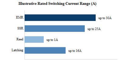 The chart above shows that electromagnetic relays typically cover the widest current range among the four types compared, which is one reason they remain common in household appliances and general automation control equipment. Solid state relays follow closely behind in current capacity while offering the added benefit of switching without mechanical wear, which is useful in applications with very frequent cycling. Reed relays sit at the lower end of the current range shown, reflecting their role in signal level switching rather than power switching, and they are usually chosen for compact instrumentation tasks rather than motor or heater control. Latching relays fall in a middle range, which suits them to applications where switching happens periodically rather than continuously, such as remote metering or access control systems. Looking across all four bars, a clear pattern emerges where higher current capacity tends to correspond with mechanical contact based designs, while lower current, higher precision tasks lean toward semiconductor or reed based designs. This pattern is a useful starting point when narrowing down a relay type, though the final choice should always also account for switching frequency, expected life cycle, and the physical mounting space available. Engineers working with automotive or instrument and meter applications, for example, often prioritize compact size and precise switching over raw current capacity. Meanwhile, industrial automation control panels may prioritize a higher current relay that can directly drive a contactor or motor starter coil. A professional manufacturer or supplier can usually provide detailed technical datasheets for a specific relay model so that current capacity is confirmed against the manufacturer's own testing data rather than general industry ranges. This distinction between general reference ranges and manufacturer verified specifications is an important step for any OEM or ODM project sourcing relays for a new product design.
Core takeaway: relay type selection should be based on required switching current, cycling frequency, and mounting space rather than a single universal specification.
How a Relay Works: Structure and Operating Principle
An electromagnetic relay is built around a few core parts: a coil, an iron core, an armature, a return spring, one or more sets of contacts, and a base with terminal pins for mounting. When current flows through the coil, it generates a magnetic field that pulls the armature toward the core, which in turn moves the attached contacts so that a normally open contact closes or a normally closed contact opens. When coil current is removed, the return spring pulls the armature back to its resting position, restoring the contacts to their original state. This simple mechanical action is what allows a small coil current to control a separate, often much larger, load circuit.
Contact Configuration Terminology
Relay contact arrangements are usually described using pole and throw terminology. A single pole single throw (SPST) relay has one switch path that is either open or closed. A single pole double throw (SPDT) relay can switch a common contact between two different paths. A double pole double throw (DPDT) relay controls two independent switch paths simultaneously, which is often used when two circuits need to be switched together, such as reversing the direction of a small motor. Choosing the correct pole and throw configuration is one of the first steps in relay selection for a new circuit design.
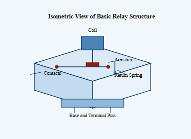
The isometric diagram above shows the general layout of an electromagnetic relay, with the coil positioned above the armature so that energizing the coil pulls the armature downward to shift the attached contacts. The base and terminal pins at the bottom represent the mounting interface, which allows the relay to be installed either through hole on a printed circuit board or plugged into a socket depending on the design. This general structure is common across many household and industrial relay models, though exact dimensions, pin layouts, and contact materials vary between manufacturers and product series.
Core takeaway: a relay's coil, armature, spring, and contacts work together so that energizing the coil physically changes the switching state of the load circuit.
Relay Applications Across Industries and Selection Criteria
Relays are used across a wide range of industries because nearly every automated system needs a way to switch a load based on a control signal. Common application areas include household electrical appliances, telecommunication systems, automation control panels, automobiles, and instruments and meters. Each application area tends to emphasize different selection criteria, which is why relay selection should always start from the specific requirements of the end application rather than a generic specification sheet.
| Application Area | Primary Selection Criteria |
|---|---|
| Household electrical appliances | Compact size, quiet operation, stable long term switching |
| Telecommunication equipment | Signal integrity, low contact resistance, fast response |
| Automation control systems | Cycling endurance, panel mounting compatibility |
| Automobile electrical systems | Vibration resistance, wide temperature tolerance |
| Instruments and meters | Precise switching, low signal loss, compact footprint |
Before looking at the chart below, it is worth noting that relay demand is generally spread across several industry categories rather than concentrated in a single sector. This distribution reflects how broadly relay based switching is used across consumer, industrial, and infrastructure equipment. The proportions shown are illustrative and intended to represent a general pattern often described in industry overviews of the relay market. They are not meant to represent exact figures for any single manufacturer or region. Viewing this distribution helps explain why relay manufacturers often serve multiple industries at the same time rather than specializing in only one.
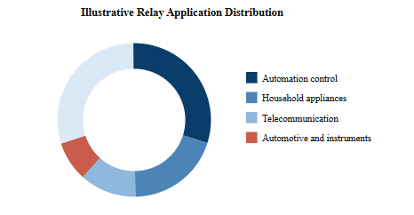
The donut chart above shows automation control taking the largest illustrative share, which aligns with how widely relays are used in industrial panels, machine control cabinets, and process automation equipment. Household appliances form the next largest segment, reflecting the long standing use of relays in devices such as washing machines, water heaters, and climate control systems. Telecommunication applications make up a smaller but consistent portion, driven mainly by signal switching needs in networking and communication equipment rather than high power switching. Automotive and instrument and meter applications together make up the remaining share, with automotive relays typically emphasizing vibration and temperature resistance while instrument relays emphasize precision and compact size. This spread across four broad categories illustrates why a relay manufacturer often maintains a diverse product range covering multiple pole and throw configurations, coil voltages, and mounting styles. For a company sourcing relays for a new product line, understanding which of these four categories most closely matches the intended use case is a useful first step before requesting samples or technical datasheets. Buyers working on cross category products, such as a telecommunication device that also needs an automotive rated component, may need to review relay specifications from more than one product family. Because relay demand is distributed rather than concentrated, professional manufacturers generally design their catalogs to serve overlapping needs across these industries. This is also why OEM and ODM relay projects often begin with a discussion of the target application category before moving to detailed technical specifications. Recognizing these general demand patterns can help procurement teams and engineers frame more focused technical questions when contacting a supplier or factory.
Core takeaway: relay applications span household, telecommunication, automation, automotive, and instrument sectors, so selection criteria should always be matched to the specific industry use case.
Comparative Analysis of Electromagnetic, Solid State, and Reed Relays
Choosing between electromagnetic, solid state, and reed relays often comes down to a small set of performance attributes: switching speed, mechanical life, isolation performance, electromagnetic interference behavior, and physical shock resistance. No single relay type performs best across every attribute, which is why comparative analysis is a useful step before finalizing a design.
| Attribute | Electromagnetic Relay | Solid State Relay | Reed Relay |
|---|---|---|---|
| Switching Speed | Moderate | Fast | Fast |
| Mechanical Wear | Present | None | Minimal |
| Electrical Isolation | Strong | Moderate | Strong |
| Compact Size | Moderate | Moderate | Compact |
| Shock Resistance | Moderate | High | Moderate |
The radar chart below translates the comparison table into a visual format so that the tradeoffs between the three relay types can be seen at a glance. Each axis represents one performance attribute on a simple relative scale rather than an exact measured value. This kind of visualization is useful for quickly identifying which relay type leans toward which strengths. It also highlights that no single relay type dominates across every axis, reinforcing the idea that relay selection is application specific. Reviewing the shape formed by each relay type on the chart can help engineers explain design tradeoffs to colleagues or clients during a technical review.
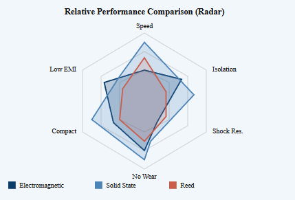
Looking at the radar chart, the solid state relay shape extends furthest along the speed and no wear axes, which visually confirms why solid state relays are often chosen for applications involving frequent or continuous switching cycles. The electromagnetic relay shape extends further along the isolation and shock resistance axes, reflecting its strong mechanical separation between control and load circuits and its general durability under physical stress. The reed relay shape is more compact overall but extends notably along the compact size axis, consistent with its common use in space constrained instrument and signal switching applications. None of the three shapes covers the full radar area, which visually reinforces that every relay type involves some tradeoff. For example, gaining fast switching and no mechanical wear with a solid state relay often means a comparatively lower isolation rating than an electromagnetic relay of similar size. Similarly, gaining strong isolation and shock resistance with an electromagnetic relay generally means accepting some mechanical wear over the product life. Reed relays offer a middle ground for signal level applications but are less suited to switching higher power loads compared with the other two types. When reviewing this chart with a manufacturer or supplier, it can be useful to ask which attributes matter most for a specific project, since a supplier can often recommend a relay series that leans toward the priorities identified. Automation control panels that need long service life under continuous cycling, for instance, may lean toward solid state options, while automotive or vibration heavy environments may lean toward electromagnetic options with reinforced contact design. This kind of attribute based comparison is generally more useful for OEM and ODM sourcing decisions than comparing relays purely on a single specification such as rated current.
Core takeaway: electromagnetic, solid state, and reed relays each offer a different balance of speed, wear resistance, isolation, and size, so the right choice depends on which attributes matter most for the application.
Mounting Configurations and Adoption Patterns
Relays are also differentiated by how they are physically mounted into a system. The four most common mounting styles are printed circuit board (PCB) mount, panel mount, plug-in socket mount, and DIN rail mount, each suited to a different type of installation and maintenance approach.
PCB Mount
Soldered directly onto a circuit board, common in compact appliance and instrument designs. Panel Mount
Mounted on an enclosure panel, often used in control cabinets requiring front access. Plug-in Socket
Inserted into a base socket, allowing quick replacement without rewiring. DIN Rail Mount
Clips onto a standard rail, widely used in automation control enclosures.
Before viewing the line chart below, it is helpful to understand that relay mounting preferences have shifted gradually over recent years as automation control panels and compact appliance designs have evolved. Plug-in socket mounting has traditionally been favored where quick field replacement is a priority, such as in industrial control panels. PCB mount relays have grown in relative use alongside the broader trend toward more compact circuit board based product designs. The trend line below is an illustrative representation of this general shift rather than an exact statistic from a specific market study. It is intended to show a directional pattern rather than a precise figure.
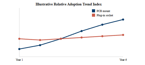
The line chart above shows PCB mount adoption trending upward at a steadier pace across the illustrative time period, which aligns with the broader move toward more compact, board integrated designs in household appliances and instruments and meters. Plug-in socket mount adoption remains comparatively flat, suggesting it continues to hold a stable role rather than declining sharply, largely because field replaceable relays are still valued in industrial automation control panels where downtime needs to be minimized. This pattern suggests that PCB mount and plug-in socket mount relays are not necessarily competing directly but instead serving different installation philosophies. A product designed for a sealed household appliance is unlikely to need field replacement in the same way an industrial control cabinet does, which is why PCB mount growth does not necessarily indicate a decline in plug-in socket relevance. For OEM and ODM projects, this distinction is often more important than the general trend line itself, since the mounting style should ultimately be dictated by the maintenance model of the end product rather than a general industry direction. Manufacturers offering both mounting styles across their product range are generally able to support both new compact designs and existing field maintained systems. When comparing quotations or samples from different suppliers, it can be useful to confirm which mounting styles are available within the same relay series, since this can simplify future design changes without requiring a completely new sourcing search. DIN rail mount relays, while not shown separately in this simplified chart, generally follow a similar steady pattern tied closely to automation control cabinet designs. Overall, the mounting configuration trend should be treated as one input among several when planning a new relay based product, alongside switching type, contact rating, and application environment.
Core takeaway: mounting style should match the maintenance model of the end product, with PCB mount suited to compact sealed designs and plug-in or DIN rail mount suited to field serviceable panels.
Maintenance and Longevity Guidance for Relays
Even a well built relay benefits from periodic inspection, particularly in applications where the relay switches frequently or operates in a demanding environment. Following a basic maintenance routine can help extend the practical service life of a relay based system and reduce unplanned downtime.
- Periodically inspect contact surfaces for discoloration or pitting, which can indicate arcing from switching loads beyond the rated current.
- Confirm coil voltage remains within the rated range, since an undervoltage condition can cause unreliable armature movement over time.
- Keep relays protected from excessive dust, moisture, and vibration, especially in automotive and outdoor automation control installations.
- Test switching response periodically in critical systems to confirm the relay is still actuating within an acceptable response time.
- Replace relays proactively in high cycle applications once they approach their rated mechanical or electrical operation count.
In general, electromagnetic relays are more sensitive to contact wear over time because their switching action involves physical movement, so inspection routines for electromagnetic relays often focus more heavily on contact condition than those for solid state relays. Solid state relays, having no moving parts, are generally more resistant to mechanical wear but can still be affected by heat buildup, so ensuring adequate heat dissipation around a solid state relay is an important part of its maintenance consideration. For automation control panels with many relays operating together, a simple periodic visual and functional check across the panel can often catch early warning signs before a full system failure occurs. Working with a professional manufacturer or supplier that provides clear technical datasheets can also make maintenance planning easier, since rated mechanical and electrical life figures give a practical benchmark for scheduling proactive replacement in high cycle applications.
Core takeaway: routine contact inspection, coil voltage checks, and proactive replacement in high cycle applications are practical steps for extending relay service life.
Sourcing Reliable Relays from Manufacturers and Suppliers
When sourcing relays for a new product design or a replacement part program, buyers typically look beyond a basic datasheet and evaluate the manufacturer's overall production capability, testing standards, and certification history. A professional manufacturer that specializes specifically in relay research, development, and production is often better positioned to support OEM and ODM projects than a general component trading company, since in house engineering knowledge tends to translate into more consistent product quality and clearer technical support.
One example of this kind of specialized relay manufacturer is Ningbo Helishun Electron Co., Ltd., founded in 2000 and located in Ningbo City on the coastline of the East Sea, covering a production area of about 8800 square meters. The company focuses specifically on researching, developing, and producing relays, and has built its quality management system around advanced testing equipment sourced from both domestic and international suppliers, having passed ISO9001:2015 quality system certification. Its relay products have obtained certification from UL, TUV, CE, and CQC, and comply with EU RoHS requirements, which are the kinds of certifications international buyers typically check when evaluating a factory as a potential OEM or ODM partner. The company's relay products are used across household electrical appliances, telecommunication, automation control, automobiles, and instruments and meters, matching the broad application range discussed earlier in this article.
For buyers comparing a China manufacturer, China supplier, or China factory as a sourcing option, it is generally useful to request sample units alongside technical datasheets so that contact resistance, coil voltage tolerance, and mechanical life can be independently verified before committing to a larger order. A wholesale supplier or exporter that regularly serves OEM and ODM customers is also more likely to be familiar with customizing pole and throw configuration, coil voltage, and mounting style to match a specific product requirement. Working with an established relay manufacturer or producer that maintains consistent quality management practices can help reduce the technical risk involved in integrating a new relay component into an existing product line, particularly for buyers who are sourcing relays for export focused manufacturing rather than a single domestic project.
Core takeaway: evaluating a relay manufacturer's certifications, testing practices, and OEM or ODM experience is a practical way to reduce sourcing risk before finalizing a supplier.
Frequently Asked Questions
Q1: What is the basic function of a relay?A relay uses a small control signal to open or close a separate circuit, allowing low power control equipment to safely switch a larger or electrically isolated load. |
Q2: What is the difference between electromagnetic and solid state relays?Electromagnetic relays use a coil and moving armature to switch mechanical contacts, while solid state relays use semiconductor components with no moving parts, generally offering faster switching without mechanical wear. |
Q3: How long do relays typically last?Service life depends on relay type, switching load, and cycling frequency; electromagnetic relays are generally rated by mechanical and electrical operation counts, while solid state relays are less affected by mechanical wear. |
Q4: Can relays be customized for OEM or ODM projects?Many relay manufacturers support OEM and ODM customization, including coil voltage, contact configuration, and mounting style, tailored to a specific product design. |
Q5: What certifications should buyers look for when sourcing relays?Common certifications include ISO9001 for quality management, along with UL, TUV, CE, CQC, and RoHS compliance depending on the target export market. |
Q6: How do I choose between SPST, SPDT, and DPDT relay configurations?The choice depends on how many separate circuit paths need to be switched; SPST suits a single on-off path, SPDT suits switching between two paths, and DPDT suits controlling two independent paths at once. |


