



 English
 中文简体
中文简体Content
- 1 How To Wire A Relay: The Direct Answer
- 2 Understanding What Each Relay Pin Actually Does
- 3 Tools And Preparation Before You Start Wiring A Relay
- 4 Step By Step: Wiring The Coil Control Circuit
- 5 Step By Step: Wiring The Load (Contact) Circuit
- 6 Why A Flyback Diode Matters When Wiring A Relay Coil
- 7 Choosing Wire Gauge For The Relay Load Circuit
- 8 Verifying A Relay Wiring Job Before Full Power
- 9 Typical Pin Layout Of A 5-Pin Relay
- 10 About Ningbo Helishun Electron Co., Ltd
- 11 Frequently Asked Questions About Wiring A Relay
How To Wire A Relay: The Direct Answer
To wire a standard 5-pin automotive-style relay, connect pin 85 to ground and pin 86 to a switched power source so the coil can be energized by a low-current control signal. Connect pin 30 to the main power supply, usually through a fuse, and connect pin 87 to the load you want to switch on, since 30 and 87 close together once the coil is energized. Pin 87a, present only on 5-pin relays, stays connected to pin 30 whenever the coil is de-energized and is only needed if a second device must run while the relay is at rest.
This coil-then-load wiring logic is the same whether the relay is controlling a fan, a fuel pump, a light circuit, or an industrial contactor coil, which is why understanding the five pin roles is the real key to wiring a relay correctly rather than memorizing one specific diagram.
- Identify the coil terminals, usually marked 85 and 86, and the contact terminals, marked 30, 87, and 87a.
- Wire pin 86 to switched power and pin 85 to ground to form the low-current control circuit.
- Wire pin 30 to the main power source through an appropriately rated fuse.
- Wire pin 87 to the load that should turn on when the relay is energized.
- Leave pin 87a disconnected unless a second device needs power while the relay is at rest.
- Add a flyback diode across the coil terminals if the control circuit uses a transistor, relay driver, or sensitive switching electronics.
Understanding What Each Relay Pin Actually Does
A relay contains two electrically separate circuits inside one housing: a low-current control circuit built around the coil, and a higher-current load circuit built around the switching contacts. According to a widely referenced automotive relay pinout guide, pins 85 and 86 form the coil circuit and have no fixed polarity, meaning the coil will energize regardless of which terminal is grounded and which is switched, while the contact side made up of pins 30, 87, and 87a is where wiring order genuinely affects circuit behavior.
| Pin | Name | Function |
|---|---|---|
| 85 | Coil terminal | Typically wired to ground |
| 86 | Coil terminal | Typically wired to switched power |
| 30 | Common (COM) | Main power feed into the load circuit |
| 87 | Normally Open (NO) | Connects to 30 when the coil is energized |
| 87a | Normally Closed (NC) | Connects to 30 when the coil is de-energized |
A four-pin relay follows the same logic but omits pin 87a entirely, so it can only be wired as a normally open switch. As one relay wiring reference puts it, a four-pin relay is essentially a five-pin relay without the normally closed terminal, and the wiring for the remaining four pins is identical between the two versions.
Tools And Preparation Before You Start Wiring A Relay
A small set of tools makes relay wiring far more reliable, particularly for automotive or industrial control panel work where vibration and heat cycling can loosen a poor connection over time. Gathering everything before starting also reduces the temptation to substitute an undersized wire or connector partway through the job.
- A relay socket or mounting base matched to the relay's pin layout
- Wire sized appropriately for the load current, with heavier gauge on the pin 30 to pin 87 path
- An inline fuse and fuse holder for the pin 30 power feed
- Crimp connectors or a soldering iron, plus heat shrink or electrical tape for insulation
- A multimeter to confirm pin identification and continuity before applying power
- A flyback diode rated for the coil voltage, if the control circuit is driven by a transistor or microcontroller output
Step By Step: Wiring The Coil Control Circuit
The coil circuit is the low-current side of the relay and is usually the simplest part to wire correctly. Because pins 85 and 86 have no fixed polarity, either terminal can be grounded and either can be switched, though the common convention documented in automotive wiring guides is to ground pin 85 and connect pin 86 to the switched power source coming from a dashboard switch, relay driver, or control unit output.
Coil Circuit Wiring Steps
- Connect pin 85 to a reliable ground point, close to the relay to minimize voltage drop.
- Connect pin 86 to the output of the switch or control device that should activate the relay.
- Confirm the switch or control output can supply the coil's rated current without overheating.
- Add a flyback diode across pins 85 and 86, oriented so it blocks current during normal operation and conducts only when the coil is switched off.
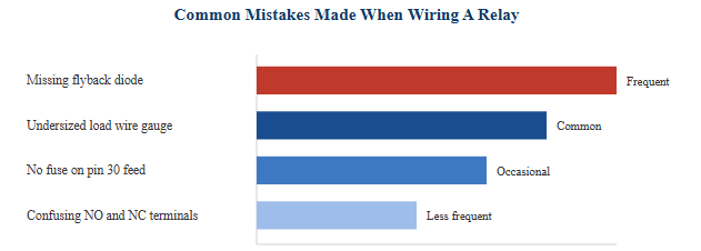 This horizontal bar chart summarizes wiring mistakes that repair and DIY guides most often flag when a newly installed relay circuit does not behave as expected, ranked qualitatively rather than as measured statistics. A missing flyback diode on the coil is described most frequently, because the resulting voltage spike is often invisible to the installer while still shortening the life of nearby switching electronics such as transistors or relay drivers. Undersized wire on the load path between pin 30 and pin 87 is the next most common issue, since a wire rated for signal-level current will overheat when asked to carry the full current of a motor, fan, or lighting load. Skipping the inline fuse on the pin 30 feed removes an important safety margin, since without it a downstream short can overheat the wiring harness rather than simply blowing a replaceable fuse. Confusing the normally open and normally closed contacts appears less often but still causes real problems, typically showing up as a device that runs constantly instead of only when triggered, or the reverse. Working through the coil circuit first and the load circuit second, exactly as described in this article, is one of the simplest ways to avoid this entire category of mistakes.
Step By Step: Wiring The Load (Contact) Circuit
Once the coil circuit is wired, move on to the load circuit, which is the part of the relay actually carrying power to the device being switched. Pin 30 should be connected to the main power supply, ideally through an inline fuse sized just above the load's normal operating current, so that a fault downstream trips the fuse rather than damaging the wiring harness or the relay contacts themselves.
Pin 87 is the normally open contact and should be wired to whichever device is meant to turn on when the relay activates, such as a fan motor, a fuel pump, or a lighting circuit. If the application needs a second device to stay powered only while the relay is at rest, that device is wired to pin 87a instead, since 87a is connected to pin 30 by default and disconnects the moment the coil energizes.
| Relay State | Pin 30 to Pin 87 (NO) | Pin 30 to Pin 87a (NC) |
|---|---|---|
| Coil de-energized | Open | Closed |
| Coil energized | Closed | Open |
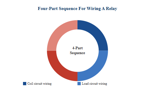 This donut chart represents the four equally weighted stages of a complete relay wiring job rather than a measured proportion of installation time. The first stage is coil circuit wiring, connecting pins 85 and 86 to ground and switched power so the electromagnet can be triggered by a low-current signal. The second stage is load circuit wiring, connecting pin 30 to the main power feed and pin 87 to the device that should be switched on. The third stage covers protection and fusing, including the inline fuse on the pin 30 feed and the flyback diode across the coil terminals, both of which guard the rest of the circuit against faults and voltage spikes. The fourth stage is verification, using a multimeter to confirm pin identification and continuity before the relay is ever exposed to full working voltage and current. Treating relay wiring as these four distinct stages, rather than one continuous task, makes it much easier to isolate a problem if the finished circuit does not behave as expected.
Why A Flyback Diode Matters When Wiring A Relay Coil
A relay coil is an inductive load, and when current through an inductor is suddenly interrupted, the collapsing magnetic field generates a brief but very high voltage spike, commonly called inductive kickback. Technical guidance on flyback diode design describes this spike as capable of reaching hundreds of volts even from a coil that normally operates at only 12 volts, which is more than enough to damage a switching transistor, a relay driver IC, or a microcontroller output pin if the coil is driven directly by that circuit.
A flyback diode wired in reverse polarity across the coil terminals gives that collapsing magnetic field a safe path to discharge through instead. During normal operation the diode is reverse-biased and has no effect on the circuit, but the instant the coil is switched off, the polarity of the spike forward-biases the diode and lets the stored energy dissipate gradually as heat within the coil's own resistance rather than as a damaging voltage transient elsewhere in the circuit. This protection is considered standard practice whenever a relay coil is switched by solid-state electronics rather than a simple mechanical switch, since a basic toggle switch or mechanical relay contact is generally more tolerant of the spike than a semiconductor device is.
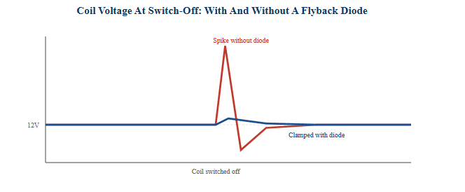 This line chart is an illustrative waveform, not a measured oscilloscope trace, showing the general shape of the voltage spike that occurs at the moment a relay coil is switched off. The red line represents the coil circuit without a flyback diode, where the voltage briefly spikes well above the normal supply level before settling back down, and it is this brief high-voltage excursion that can exceed the safe operating voltage of a driving transistor or integrated circuit. The blue line represents the same coil circuit with a flyback diode in place, where the diode clamps the voltage close to the supply rail plus a small diode forward-voltage offset, avoiding the sharp excursion entirely. The width and height of the uncontrolled spike depends on the coil's stored energy and the speed of the switching device, which is why faster electronic switches generally need flyback protection even more than slower mechanical ones. The gradual decay shown on the clamped line reflects how the diode allows the coil's stored energy to dissipate steadily through the coil's own resistance rather than escaping as a sudden transient. This comparison is the core reason flyback diode installation is treated as a standard step in relay wiring guides whenever a coil is driven by solid-state switching electronics.
Choosing Wire Gauge For The Relay Load Circuit
The wire connecting pin 30 to the power source and pin 87 to the load must be sized for the actual current the load draws, not just for convenience, since undersized wire can overheat, increase voltage drop, and in some cases create a fire hazard. As a general reference used across automotive wiring guides, larger loads require progressively heavier wire gauge, and the fuse protecting the circuit should always be rated below the wire's safe continuous current capacity.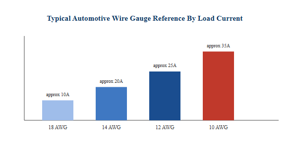
This bar chart presents general, illustrative wire gauge reference points that commonly appear in automotive wiring guidance, and actual ampacity always depends on wire insulation type, bundle size, and ambient temperature, so a manufacturer's wire gauge chart should be consulted for a specific installation. Lighter loads such as small indicator lights or low-power switching circuits are typically served well by 18 AWG wire. Moderate loads such as driving lights or small pumps generally call for 14 AWG wire to keep voltage drop and heating within a safe range. Heavier loads such as larger fans or auxiliary lighting bars are usually paired with 12 AWG wire, and high-current accessories may require 10 AWG or heavier. The bar heights in this chart increase together with load current specifically to reinforce that the wire between pin 30 and pin 87 should always be selected to match the load, never left at whatever gauge happens to be on hand, since this wire carries the relay's full switched current rather than the small signal current used on the coil side.
Verifying A Relay Wiring Job Before Full Power
Before connecting a freshly wired relay circuit to full battery or mains power, a short verification pass with a multimeter can catch a wiring mistake while it is still easy to fix. Set the meter to continuity mode and confirm that pin 30 and pin 87a show continuity with the coil de-energized, and that pin 30 and pin 87 show continuity only once rated voltage is applied across pins 85 and 86.
- Confirm coil polarity is not required, since pins 85 and 86 will work in either orientation
- Confirm the fuse on the pin 30 feed matches the wire and load rating, not just the relay's maximum rating
- Confirm the flyback diode is oriented correctly, since a reversed diode can short the coil circuit
- Listen for a single clean click when the coil is energized, rather than buzzing or chattering
- Recheck all crimped or soldered joints for a secure mechanical connection before final installation
Typical Pin Layout Of A 5-Pin Relay
The diagram below shows the general pin arrangement common to standard 5-pin electromechanical relays used in automotive, household appliance, and automation control wiring, illustrating how the coil circuit and load circuit terminals are laid out relative to one another.
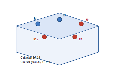
This isometric schematic illustrates the general pin layout found on standard 5-pin electromechanical relays rather than a specific product photograph. The two blue terminals represent the coil pins, 85 and 86, which form the low-current control circuit responsible for energizing the internal electromagnet. The three red terminals represent the contact pins, with pin 30 serving as the common feed and pins 87 and 87a serving as the normally open and normally closed switching outputs respectively. Many relay housings position pin 30 set apart from the 87 and 87a pair specifically so it can be identified visually during installation without needing to consult a datasheet every time. Seeing the coil pins and contact pins grouped separately in this diagram reinforces why the two circuits should always be wired, fused, and verified as distinct systems rather than as a single continuous circuit. This layout is broadly consistent across many relay manufacturers, though the exact base and socket shape can vary between relay families and should always be cross-checked against the specific relay's datasheet.
About Ningbo Helishun Electron Co., Ltd
Ningbo Helishun Electron Co., Ltd was founded in 2000 and is located in Ningbo City, on the eastern coastline of China facing the East Sea. The company now covers 8,800 square meters and specializes in researching, developing, and producing relays, holding an established position within the relay manufacturing market.
The company has introduced advanced technology and testing equipment from both domestic and international sources and has built a dependable quality management system, including ISO 9001:2015 quality system certification. Product characteristics and mounting layouts are kept consistent with comparable relay products from other regions, and the company's relays have obtained UL, TUV, CE, and CQC certification while complying with EU RoHS requirements. Helishun brand relays are supplied to both domestic and overseas markets and are used across household electrical appliances, telecommunication equipment, automation control systems, automotive applications, and instrumentation and metering devices.
The company applies careful manufacturing management across its production process and welcomes visits from domestic and international customers, as well as OEM and ODM partners interested in broader cooperation on relay development and supply.
Frequently Asked Questions About Wiring A Relay
Q1: Does it matter which coil pin I ground, 85 or 86?
No. The coil terminals have no fixed polarity, so the relay will energize correctly regardless of which pin is grounded and which is switched. The common convention is to ground pin 85 and switch pin 86, mainly for wiring consistency across a project.
Q2: Can I use a 5-pin relay in place of a 4-pin relay?
Yes. A 5-pin relay can replace a 4-pin relay by simply leaving the extra 87a terminal disconnected, as long as the coil voltage and contact current ratings match the application's requirements.
Q3: Do I always need a flyback diode when wiring a relay?
A flyback diode is strongly recommended whenever the coil is driven by a transistor, relay driver module, or microcontroller output, since these components are more sensitive to the voltage spike created when the coil switches off. A simple mechanical toggle switch is generally more tolerant of this spike, though a diode is still good practice.
Q4: What happens if I wire the load to pin 87a instead of pin 87 by mistake?
The device would receive power only while the relay is at rest and would turn off once the coil energizes, which is the opposite of typical intended behavior. Double-checking the pin labels and confirming NO and NC states with a multimeter before final installation prevents this mix-up.
Q5: Where should the relay be mounted once it is wired?
A relay should be mounted in a dry, protected location away from extreme heat and direct water exposure, with the wiring routed and secured to avoid chafing against sharp edges or hot surfaces over time.


