



 English
 中文简体
中文简体Content
- 1 How To Test A Relay With A Voltmeter: The Direct Answer
- 2 What Happens Inside A Relay While It Switches
- 3 Tools And Safety Preparation Before You Start Relay Testing
- 4 Step By Step: Testing Relay Coil Resistance With A Voltmeter
- 5 Step By Step: Testing Relay Contact Continuity And Resistance
- 6 Testing A Relay Under Energized, Live Conditions
- 7 Reading And Interpreting Contact Resistance Results
- 8 Common Mistakes That Produce False Voltmeter Readings
- 9 How Voltmeter Testing Differs Across Relay Types
- 10 When A Relay Should Be Replaced Rather Than Reused
- 11 Typical Internal Structure Of An Electromechanical Power Relay
- 12 About Ningbo Helishun Electron Co., Ltd
- 13 Frequently Asked Questions About Testing Relays With A Voltmeter
How To Test A Relay With A Voltmeter: The Direct Answer
To test a relay with a voltmeter, set the meter to the resistance (ohms) range first and measure across the two coil terminals. A healthy relay coil should read a stable resistance value, usually somewhere between 50 and 500 ohms depending on the rated coil voltage, and it should never read infinite (open circuit) or near zero (shorted turns). Next, switch the meter to continuity or resistance mode and check the switching contacts: a normally open (NO) contact should show infinite resistance with the coil de-energized and near-zero resistance once rated coil voltage is applied, while a normally closed (NC) contact behaves the opposite way.
This two-part sequence, coil check followed by contact check, is the core of almost every relay testing procedure used in automation control, household appliance, and automotive electronics work. A relay that passes both checks is generally safe to reinstall, while a relay that fails either check should be treated as suspect and scheduled for replacement rather than continued service.
- Isolate the relay from live power before probing the coil terminals.
- Set the voltmeter/multimeter to the ohms (resistance) function and measure coil resistance.
- Compare the reading with the value printed on the relay label or datasheet.
- Switch to continuity mode and check the NO and NC contact terminals with the coil de-energized.
- Apply the rated coil voltage and re-check the same contact terminals to confirm they switch state.
- Inspect visually for discoloration, pitting, or a burnt smell before returning the relay to service.
What Happens Inside A Relay While It Switches
An electromechanical relay is built around two functional sections: the coil circuit and the contact circuit. When rated voltage is applied to the coil terminals, the coil generates a magnetic field that pulls an armature toward the core, and this mechanical motion physically moves the switching contacts from their resting position to their actuated position. Because the coil side and the contact side are electrically isolated from one another, a relay lets a low-power control signal safely switch a separate, often higher-power, load circuit.
Understanding this two-circuit structure matters for voltmeter testing because a relay can fail on the coil side, the contact side, or both, and each failure produces a different meter reading. A relay with an open coil will never actuate even though the contacts themselves may still be mechanically sound, while a relay with welded or pitted contacts may have a perfectly healthy coil yet fail to interrupt the load circuit. Testing both sides separately, rather than only listening for a click, is what makes voltmeter-based relay testing reliable for troubleshooting relay circuits.
Tools And Safety Preparation Before You Start Relay Testing
A basic relay voltmeter test requires very little equipment, which is one reason this method is widely used for field diagnostics of household appliance, telecommunication, and automation control relays. Before probing any terminal, disconnect the circuit from its power source and, where possible, remove the relay from its socket or PCB so that parallel paths on the board do not distort the resistance reading.
- A digital multimeter or voltmeter with resistance and continuity modes
- The relay datasheet or the printed coil voltage and pin-out on the relay body
- A regulated DC or AC power source matching the rated coil voltage, for the energized test
- Insulated test leads and, when working near live circuits, appropriate personal protective equipment
- A clean, dry work surface and good lighting to inspect contacts visually
According to a published relay verification procedure from TE Connectivity's diagnostic guidance, the standard sequence when a relay fails to operate or is heard buzzing is to first measure coil resistance and compare it against the specification before moving on to contact-side checks, and to allow a relay that reads slightly out of specification to sit for roughly an hour before retesting in case the removal process or an applied voltage temporarily warmed the coil. This ordering avoids condemning a relay based on a reading that was only temporarily skewed by heat.
Step By Step: Testing Relay Coil Resistance With A Voltmeter
Coil resistance testing is usually the first and fastest relay test because an open or shorted coil immediately explains why a relay will not actuate at all. Set the meter to the ohms range, touch the two probes to the coil terminals (commonly labeled A1/A2 or 85/86 depending on the relay family), and read the displayed value.
| Rated Coil Voltage | Typical Resistance Range | Meter Reading If Open | Meter Reading If Shorted |
|---|---|---|---|
| 5V DC | approx. 50 to 90 ohms | Infinite (OL) | Near 0 ohms |
| 12V DC | approx. 100 to 400 ohms | Infinite (OL) | Near 0 ohms |
| 24V DC | approx. 300 to 500 ohms | Infinite (OL) | Near 0 ohms |
Coil resistance is also sensitive to temperature. Published engineering documentation on relay-based switching circuits notes that coil resistance in a typical relay can shift by more than 20 percent as the coil temperature rises from around 25 degrees Celsius to 50 degrees Celsius, since the coil current and resulting magnetic pull depend directly on that resistance. This is a useful fact to keep in mind when a coil reading falls just outside the datasheet range: letting the relay cool and retesting is a reasonable next step before concluding the coil has failed.
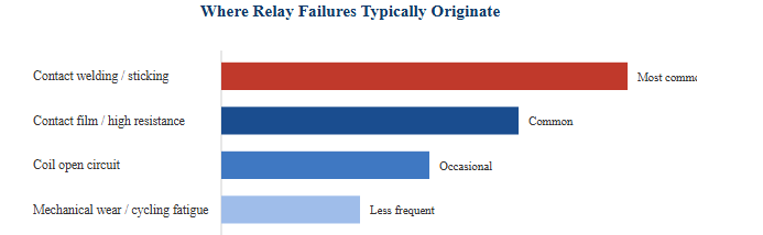
This horizontal bar chart summarizes how relay failures are typically distributed across contact and coil issues, based on findings summarized in a 2017 relay failure analysis technical report referenced by Plant Engineering. Contact-related failures, especially contacts that weld shut or stick together and stop switching correctly, are described as the most common failure mode identified across industry failure databases. Contact surfaces that build up a non-conductive film from oxidation or material off-gassing form the next largest group, since that film raises contact resistance without necessarily preventing the relay from moving. Coil opening, usually from heat damage to the winding insulation or corrosion at the coil-to-terminal connection, appears less often but still accounts for a meaningful share of returned relays. General mechanical wear from repeated switching cycles rounds out the picture and becomes more significant as a relay approaches its rated electrical life. This distribution is the reason a complete voltmeter test always checks the contacts as carefully as the coil rather than assuming a silent relay is simply a coil problem.
Step By Step: Testing Relay Contact Continuity And Resistance
Once the coil has passed its resistance check, move on to the switching contacts. With the coil de-energized, set the meter to continuity mode and touch the probes to the common terminal and the normally open terminal; a healthy NO contact will show no continuity (open circuit) at this point. Then test the common terminal against the normally closed terminal; a healthy NC contact will show continuity here instead.
For a more precise reading, switch the meter to the lowest resistance range and measure the contact resistance while the contact is closed. A widely cited troubleshooting reference for relay circuits notes that a closed contact reading of less than 0.1 ohm is generally considered healthy, while higher readings point toward wear, contamination, or early-stage arcing damage on the contact surface. Contact resistance testing is particularly useful because it can flag a relay that still switches mechanically but no longer passes current cleanly, a condition that a simple continuity beep can miss.
NO Versus NC Contact Behavior At A Glance
| Contact Type | Coil De-energized | Coil Energized |
|---|---|---|
| Normally Open (NO) | No continuity | Continuity present |
| Normally Closed (NC) | Continuity present | No continuity |
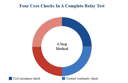 This donut chart represents the four equally weighted checks that make up a complete relay voltmeter test rather than a measured statistic, and it is meant as a visual checklist rather than a probability figure. The first quarter is the coil resistance check, which catches open or shorted windings before any contact testing begins. The second quarter is the de-energized contact continuity check, confirming the NO and NC terminals sit in their correct resting state. The third quarter is the low-resistance contact check performed while the contact is closed, which reveals contamination or early arcing damage that a simple beep test would miss. The fourth quarter is the energized function check, where rated coil voltage is applied and the contacts are re-measured to confirm they actually switch under real operating conditions, closing the loop on a full diagnostic sequence.
Testing A Relay Under Energized, Live Conditions
A relay can pass both a coil resistance test and a de-energized continuity test and still fail in service, which is why an energized function test is the final and most conclusive step. With the meter still connected across the relevant contact terminals in continuity or low-resistance mode, apply the rated coil voltage briefly to the coil terminals from a regulated supply and confirm that the reading flips as expected, from open to closed for an NO contact or from closed to open for an NC contact.
A documented contact verification approach from TE Connectivity's relay diagnostic guidance describes energizing the relay coil at its minimum rated voltage while a series resistor and indicator lamp confirm current is actually flowing through the closed contact, rather than relying on continuity alone. Applying only the minimum rated voltage, rather than an overvoltage, during this step helps avoid stressing a coil that may already be marginal, and listening for a distinct, single click during actuation is a useful secondary confirmation that the armature is moving cleanly rather than chattering or sticking partway.
Reading And Interpreting Contact Resistance Results
A single contact resistance reading is useful, but tracking how that reading changes over the life of a relay gives a much clearer picture of remaining service life. Published guidance on reed relay contact behavior describes a typical new-condition contact resistance in the range of 50 to 150 milliohms, with readings between roughly 150 and 500 milliohms suggesting the relay is aging but still usable, readings from about 500 milliohms up to 2 ohms suggesting replacement should be planned for accuracy-sensitive circuits, and readings above 2 ohms suggesting the relay is at the end of its useful life. General-purpose electromechanical power relays are not identical to reed relays, but the same rising-resistance pattern applies, so treating these bands as directional reference points rather than exact universal limits is the safer approach.
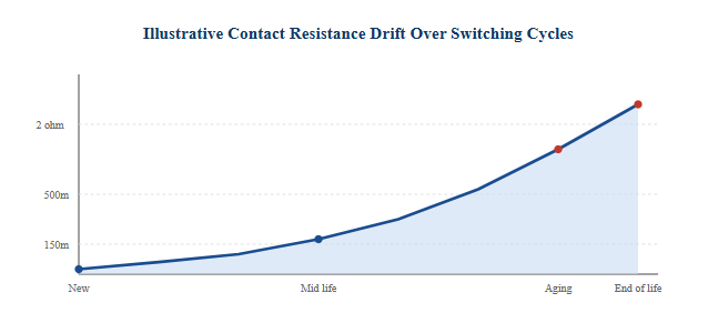 This area chart illustrates the general upward drift in contact resistance that a relay tends to show as it accumulates switching cycles, using the reference bands described above as horizontal guides. A new relay typically starts well below the 150 milliohm line, and readings stay in that low band for a large portion of the component's rated electrical life. As surface film, minor pitting, and material transfer accumulate from repeated arcing at each switch event, the resistance climbs gradually rather than jumping suddenly, which is why a single test at one point in time cannot substitute for periodic retesting in critical circuits. Once a relay's readings cross into the 500 milliohm to 2 ohm band, the curve in this chart is drawn steeper to reflect how resistance growth tends to accelerate as contact damage compounds. Logging resistance readings at scheduled intervals, rather than testing only after a fault appears, is the most reliable way to catch this trend early in automation control and instrumentation applications where a marginal contact can cause intermittent faults long before it fails outright.
| Reading | General Interpretation |
|---|---|
| Under 150 milliohms | Consistent with a new or lightly used contact |
| 150 to 500 milliohms | Aging but generally still functional; monitor |
| 500 milliohms to 2 ohms | Plan replacement, especially in accuracy-sensitive circuits |
| Above 2 ohms | Treat as end of life |
Common Mistakes That Produce False Voltmeter Readings
Several routine mistakes can make a perfectly good relay look faulty, or worse, let a marginal relay pass testing. Testing a relay while it is still soldered into a board without isolating it can introduce parallel resistance paths from surrounding components, skewing the ohms reading in either direction. Leaving the meter in the wrong mode, such as reading DC voltage while trying to check resistance, is another frequent source of confusing or nonsensical results.
- Not isolating the circuit from power before probing, risking meter damage or an inaccurate reading
- Testing coil resistance immediately after the relay was energized, before it has cooled
- Ignoring parallel paths created by other components still connected on the same board
- Using worn or oxidized test leads that add their own resistance to a low-ohm contact reading
- Judging a relay only by whether it clicks, without confirming the contacts actually pass current cleanly
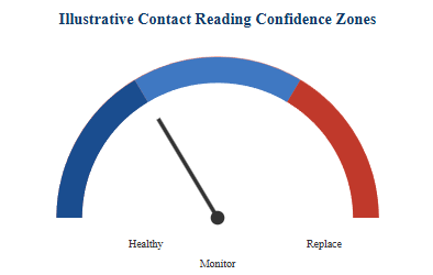 This gauge chart is a schematic representation, not a measured statistic, of how a single contact resistance reading can be sorted into a quick decision zone during field testing. The needle position illustrates a reading that falls in the healthy zone, meaning the relay can generally be returned to service without further action. The middle zone represents readings that are elevated but not yet critical, calling for a note in a maintenance log and a follow-up check at the next scheduled interval rather than immediate replacement. The zone toward the right represents readings high enough that continued use in an accuracy-sensitive or safety-related circuit is not advisable. Presenting results this way is especially useful for technicians who test many relays in sequence, since it turns a raw ohms number into a fast go or no-go decision without requiring a lookup table every time.
How Voltmeter Testing Differs Across Relay Types
The same coil-then-contact logic applies across most relay families, but a few details change depending on the construction. The table below summarizes the practical differences a technician should keep in mind when testing common relay types with a voltmeter.
| Relay Type | Coil Test Notes | Contact Test Notes |
|---|---|---|
| SPDT electromechanical | Single coil, straightforward ohms check | One NO and one NC pair to verify |
| DPDT electromechanical | Same single coil check as SPDT | Two independent contact sets to verify separately |
| Reed relay | Low coil current, use gentle probe pressure | Very low resistance expected; watch for magnetized blades |
| AC coil relay | Resistance reading only checks the winding, not inductive behavior | Same NO/NC logic as DC coil types |
When A Relay Should Be Replaced Rather Than Reused
Not every out-of-range reading means a relay must be discarded immediately, but a few signs consistently point toward replacement rather than continued use. An open coil reading that does not change after the relay has cooled indicates damaged winding insulation or a broken internal connection and cannot be repaired in the field. Contacts that remain closed on an NO terminal even with the coil fully de-energized suggest welding, a failure mode described in relay failure analysis literature as arising from large current surges through the contact surface, and this condition can leave a load circuit permanently energized, which is a safety concern rather than only a performance issue.
Visible pitting, discoloration, or a burnt odor around the contact housing are additional practical indicators worth combining with the meter readings, since a relay nearing its rated switching-cycle life will often show physical wear alongside a rising resistance trend. Keeping a simple log of coil and contact resistance values for relays in critical automation control or instrumentation circuits makes it much easier to spot this kind of gradual drift before it causes an unplanned shutdown.
Typical Internal Structure Of An Electromechanical Power Relay
The diagram below shows the general internal layout common to standard electromechanical power relays used in household appliance, automation control, and automotive applications, illustrating why the coil circuit and the contact circuit are tested as two separate systems.Coil terminals
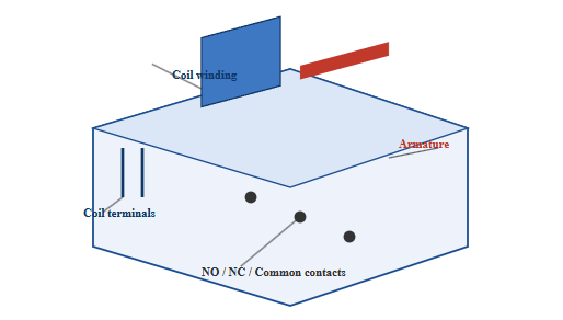
This isometric schematic illustrates the general internal arrangement found in standard electromechanical power relays rather than a specific product photograph. The coil winding sits at the core of the assembly and generates the magnetic field responsible for pulling the armature when rated voltage is applied to the coil terminals shown at the base. The armature is the moving mechanical link that transfers that magnetic pull into physical contact movement, which is why a relay with a perfectly good coil can still fail if the armature sticks or the return spring weakens over time. The normally open, normally closed, and common contact points are arranged so that only one path is closed at a time in the resting state, and testing each of these three points individually is what a full voltmeter contact test is designed to verify. Seeing this layout helps explain why coil problems and contact problems require separate meter checks rather than a single combined test, since the two failure paths are physically and electrically independent inside the housing.
About Ningbo Helishun Electron Co., Ltd
Ningbo Helishun Electron Co., Ltd was founded in 2000 and is located in Ningbo City, on the eastern coastline of China facing the East Sea. The company now covers 8,800 square meters and specializes in researching, developing, and producing relays, holding an established position within the relay manufacturing market.
The company has introduced advanced technology and testing equipment from both domestic and international sources and has built a dependable quality management system, including ISO 9001:2015 quality system certification. Product characteristics and mounting layouts are kept consistent with comparable relay products from other regions, and the company's relays have obtained UL, TUV, CE, and CQC certification while complying with EU RoHS requirements. Helishun brand relays are supplied to both domestic and overseas markets and are used across household electrical appliances, telecommunication equipment, automation control systems, automotive applications, and instrumentation and metering devices.
The company applies careful manufacturing management across its production process and welcomes visits from domestic and international customers, as well as OEM and ODM partners interested in broader cooperation on relay development and supply.
Frequently Asked Questions About Testing Relays With A Voltmeter
Q1: Can I test a relay without removing it from the circuit board?
A basic function test is possible in-circuit, but for an accurate coil or contact resistance reading it is best to isolate or remove the relay, since other components on the board can create parallel paths that distort the measurement.
Q2: What does an infinite or OL reading on the coil terminals mean?
An infinite or OL reading across the coil terminals generally indicates an open coil circuit, meaning the winding has broken internally or the connection to the terminal has failed, and the relay will not actuate.
Q3: Why does my relay click but the load still does not turn on?
A click confirms the armature is moving, but it does not confirm the contacts are passing current cleanly. Measuring contact resistance while the contact is closed can reveal a high-resistance or contaminated contact that clicks normally yet fails to carry the load current.
Q4: Is a voltmeter enough, or do I need a dedicated relay tester?
A voltmeter or multimeter with resistance and continuity modes is sufficient for most coil and contact diagnostics described here. Dedicated relay test equipment can add automated cycling and precision contact resistance measurement, which is useful for high-volume testing but not required for routine field checks.
Q5: How often should relays in a control panel be retested?
There is no single fixed interval, since it depends on switching frequency, load current, and environmental conditions. Relays used in high-cycle automation control applications generally benefit from more frequent scheduled checks than relays used in low-cycle household appliance circuits.


