



 English
 中文简体
Content
- 1 What Relay Logic Is and What It Is Not
- 2 How a Hardwired Relay Circuit Executes
- 3 Reading and Documenting Relay Ladder Diagrams
- 4 Contact Selection: Inrush, Duty Cycle and Contact Life
- 5 Relay Logic Compared with Programmable Control
- 6 Safety Interlocks, Redundancy and Voting Circuits
- 7 Interposing Relays Between Logic and Field Signals
- 8 Sourcing Relays and Sockets from a Manufacturer
- 9 Commissioning, Troubleshooting and Maintenance
- 10 Where to Go Next
- 11 FAQ: Relay Logic Questions from Designers and Buyers
- 11.1 What is relay logic used for in modern machines?
- 11.2 How many steps can a relay logic panel handle before a controller is cheaper?
- 11.3 Why does a relay contact weld closed?
- 11.4 Can relay logic be used for safety functions?
- 11.5 What should a buyer check when ordering relays and sockets?
- 11.6 Do relay logic panels need scheduled maintenance?
A machine builder calls with a familiar problem: an older control cabinet has lost two of its eight interlock relays, the original supplier discontinued the part, and the quote for a controller retrofit is three times what the customer wants to spend. The practical answer is usually to rebuild the sequence with relay logic on the same DIN rail, using relays and sockets that match the original footprint, wire numbers and rung layout. It is not glamorous work, but it is predictable, cheap to service and easy to prove out with a meter.
Relay logic is the practice of building control decisions out of relay coils, contacts and wiring instead of software. It covers everything from a single seal-in rung for a sump pump to a full step sequence with timers, interlocks and status lamps. The conclusion worth stating up front is this: where a machine needs fewer than roughly twenty control steps, runs in a hot or electrically noisy environment, and must keep working when nobody on site can edit code, hardwired relay logic is often the lower-risk choice. Above that threshold, a controller usually pays for itself, and the decision becomes an economic one rather than a technical one.
This guide looks at how relay logic circuits actually behave, how to read and document them, how to size contacts against real loads, when a controller beats a relay panel, and what to check when buying relays and sockets from a manufacturer.
What Relay Logic Is and What It Is Not
Relay logic describes control decisions built from the coil and contacts of electromechanical relays. A coil is either energised or it is not; its contacts are either closed or open. Arrange those two states in the right wiring pattern and you obtain the same AND, OR and NOT functions a logic designer would draw in a textbook, executed in copper rather than in code.
The mapping is direct, and it explains why a hardwired relay logic panel can be traced rung by rung with nothing more than a meter and a drawing:
| Logic function | Hardwired implementation | Typical use in a panel |
|---|---|---|
| AND | Two or more normally open contacts wired in series | Run permission that requires both a guard switch and a pressure switch |
| OR | Two or more contacts wired in parallel | Start command accepted from either a local button or a remote input |
| NOT | A normally closed contact placed in the current path | Stop, fault and level cut-outs |
| Latch or seal-in | An output relay contact wired in parallel with the start button | Holding a run state after the operator releases the button |
| Memory with priority | A second relay that interrupts the seal-in path | Stop-dominant sequences and latched fault indication |
| Timing | An on-delay or off-delay timer relay inserted in the rung | Changeover sequences, purge cycles, alarm delays |
What relay logic is not is a program. There is no scan cycle, no memory table, no online edit and no diagnostic code. Every decision is made by current flowing through a physical path. That is exactly why maintenance technicians trust it, and also why a complex sequence becomes awkward to modify once the panel is wired and the drawings have been issued.
It also matters that relay logic is inherently parallel. If three rungs share the same coil feed, all three evaluate at the same instant, which is a genuine advantage for interlocks but a genuine complication when two rungs try to drive the same output in opposite directions.
How a Hardwired Relay Circuit Executes
When a coil is energised, the armature does not move instantly. Typical small power relays pull in within a few milliseconds and release within a similar window, and the exact figures shift with coil voltage, temperature and the mechanical condition of the armature. In a sequence with five relays in cascade, those delays accumulate into tens of milliseconds, which is usually harmless but occasionally decisive.
Consider a simple sump control with two floats. The low-level float contact starts the pump through a seal-in rung; the high-level float opens a normally closed contact in series and breaks the seal. When the high float trips, current to the coil stops, the armature releases, the seal-in contact opens and the run lamp goes out. Nothing in that sequence requires a scan table, and a technician can confirm each step in seconds by watching the contacts change state.
Two effects deserve attention on any relay logic panel:
- Race conditions. If one rung can energise a relay while another rung can de-energise it at the same moment, the outcome depends on which contact opens first. Interlocks and mechanical stops are the usual cure.
- Contact bounce and arcing. Dry contacts bounce for a short time at make and draw an arc at break. On inductive loads the arc energy is higher, and contact material and gap size become selection criteria rather than details.
Because the logic is parallel, an interlock placed in series with a coil feed protects that coil regardless of which rung is commanding it. That single behaviour is the main reason hardwired relay logic survives in safety and interlock chains long after the rest of a machine has moved to programmable control.
Reading and Documenting Relay Ladder Diagrams
A ladder diagram for relay logic is drawn between two vertical rails. The left rail is the control supply and the right rail is the return, and each horizontal rung contains the contacts and the coil that the rung drives. Reading it correctly is a skill that pays for itself during commissioning.
- Identify the control transformer or supply first, and note whether the rung is fed from a fused branch or directly from the rail.
- Trace from the left rail to the coil, treating every normally closed contact as a break in the path when the associated relay or device is energised.
- Check the cross-reference column for each contact, which tells you which rung and which sheet the driving coil sits on.
- Confirm wire numbers at the terminal strip, because a drawing that disagrees with the panel is worse than no drawing at all.
Panel builders who work on repeat orders usually standardise rung numbering, terminal numbering and wire colours at the start of a project. It costs little during design, and it turns a two-hour troubleshooting session into a twenty-minute one. When a relay logic panel is handed over without as-built drawings, the first field modification almost always introduces an undocumented jumper, and from that point the drawing becomes unreliable.
Contact Selection: Inrush, Duty Cycle and Contact Life
The current rating printed on a datasheet is a steady-state figure, measured under defined conditions. The current a contact actually has to make and break depends on the load type, and the gap between a resistive heater and a tungsten lamp is wide enough to change which relay you should buy. Getting this wrong is one of the most common causes of welded contacts in the field.
(cold filament)
(capacitive input)
(direct on line)
contactor coils
and lamp-free loads
The pattern in the chart explains why a relay rated at ten amps may fail quickly on a lamp circuit and last for years on a resistive load. Inrush is a short event, but it happens at the moment the contacts are closing and the arc is at its most energetic, so it drives both material transfer and mechanical wear. Motors and solenoid valves add a further complication because the inductive kick at break produces a reverse voltage that sustains the arc. Capacitive-input supplies are usually the least obvious offender, since the peak current occurs in the first milliseconds and is invisible on an ordinary clamp meter. In practice, engineers apply a derating factor that reflects the load type, add an RC snubber or varistor across the coil or the contact, and choose a relay with a larger contact gap and a higher rated current than the arithmetic strictly requires.
 SPDT 5PIN 10A power relay PCB PIN HLS-32F1A:10A 125VAC 5A 250VAC/30VDC 1C:3A 250VAC/30VDCView Product →
For panel work, a 5-pin SPDT relay in the 10A class is a sensible default for control and signalling loads, while heavier output circuits should step up to a 30A frame. Duty cycle matters as much as inrush: a relay that switches ten times an hour ages very differently from one that switches ten times a minute, and the datasheet electrical life figure is normally quoted under a resistive load at a modest switching rate.
Relay Logic Compared with Programmable Control
The decision between a hardwired relay logic panel and a small controller is rarely about capability. It is about where the cost lands over the life of the machine. A relay panel concentrates cost in wiring labour and panel space; a controller concentrates cost in software, commissioning and the skills required to change it later.
| Consideration | Hardwired relay logic | Programmable control |
|---|---|---|
| Cost at low step counts | Lower hardware cost, higher wiring time | Higher hardware cost, lower wiring time |
| Changing the sequence | Rewire and update the drawing | Edit the program and download |
| Diagnostics | Visual contact state and a meter | Fault codes, status bits and trends |
| Behaviour in heat and electrical noise | Generally tolerant, no firmware involved | Requires attention to shielding and supply quality |
| Timing accuracy | Millisecond-level, affected by coil delay | Deterministic within the scan cycle |
| Skills required on site | Electrical technician | Controls or software engineer |
| Typical sweet spot | Small interlocks, safety chains, retrofit | Sequences with counters, recipes, communication |
A useful rule of thumb is that once a sequence needs counters, arithmetic, communication or more than roughly twenty discrete states, the engineering time to keep a relay ladder correct exceeds the cost of a controller. Below that line, the reverse is often true, especially on machines that are exported and serviced by local electricians rather than by the original builder.
Safety Interlocks, Redundancy and Voting Circuits
Independent interlocks are the strongest argument for keeping part of a control system hardwired. A guard switch, an emergency stop chain or a level cut-out wired directly into a coil feed continues to work when the controller is in fault, when the program is being edited, or when a sensor is misconfigured.
Voting arrangements are also straightforward in relay logic. A two-out-of-three circuit, often written as 2oo3, energises the output relay only when at least two of three input channels agree, which tolerates a single failed sensor without allowing a false trip or a false run. Wiring three contacts in series-parallel combinations produces that behaviour without any firmware, and each channel can be tested independently during commissioning.
- Keep the interlock chain physically separate from any programmable logic path.
- Use normally closed contacts for stop and fault functions so a broken wire produces a safe state.
- Add a monitoring contact on contactors and output relays where a welded contact would be dangerous.
- Document the voting logic clearly, because a 2oo3 circuit is difficult to reconstruct from a photograph of a terminal strip.
Relay logic is not automatically safe, and a properly designed interlock still depends on correct contact selection, adequate breaking capacity and disciplined wiring practice. What it does offer is transparency: a technician can see whether a channel is healthy without a laptop.
Interposing Relays Between Logic and Field Signals
Not every relay in a panel switches a motor. Many exist purely to isolate, buffer or convert a signal. An interposing relay takes a low-power output from a controller, a sensor or a communication board and presents a clean, isolated contact to the field circuit. That separation protects sensitive electronics from inductive kickback and lets a low-current logic output control a load it could never drive directly.
Signal-level relays are chosen differently from power relays. Contact resistance, minimum switching capacity and dielectric strength matter more than breaking capacity, because the loads are typically a few amps at most and often only milliamps. A mini telecom-style relay with a 2A or 3A contact rating and a compact 6-pin footprint is a common answer when board space is limited but isolation is still required.
 SPDT 6PIN 2A mini telecom relay PCB PIN HLS6-23FMax Switching VoltageView Product →
When specifying interposing relays, confirm three things: the coil voltage and current that the driving output can supply, the minimum load the contact can switch reliably, and the pin arrangement on the existing board. Sealed construction and gold-plated or adequately rated contact materials help where the signal current is very low, since a contact that works perfectly at 2A may become unreliable at 10mA if the surface film cannot be broken down.
Sourcing Relays and Sockets from a Manufacturer
Once the circuit is designed, the procurement decision determines how the panel behaves five years later. Buying from a relay manufacturer rather than a general distributor matters most when you need consistent contact materials, stable pin layouts across production batches, and documentation that satisfies an approval body.
The practical checklist for any relay logic project covers the relay body and the socket together. Relays and sockets are a matched pair: an 8-pin DPDT relay and an 11-pin three-pole relay look similar in a catalogue photograph but require different socket bases, different retaining clips and different terminal numbering. Ordering them from the same supplier removes a whole class of assembly errors.
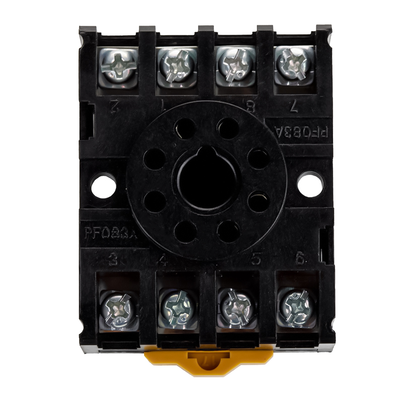 HLS-PF083A relay socket for MK2PNingbo Helishun Electron Co.,Ltd.View Product →
Several further points are worth confirming before a purchase order is issued:
- Certification coverage. UL, TUV, CE, CQC and RoHS documentation should be available for the specific part number, not only for the product family.
- Compatibility with the installed layout. Where a panel is being retrofitted, pin positions and overall dimensions must match the existing footprint so that wiring does not have to be re-routed.
- Contact form and current class. SPDT and DPDT versions in the same series should be available so a design can be extended without changing sockets.
- Supply continuity. A supplier that also operates as an OEM and ODM partner is more likely to hold tooling and keep a long-running part available.
- Quality system. An ISO 9001 certified manufacturing base with in-house test equipment gives a defensible answer when a customer audit arrives.
For buyers in North America and Europe, working directly with an overseas manufacturer can reduce unit cost, but the savings only hold if documentation, packaging and labelling meet the importer's requirements. Wholesalers and distributors usually add value in mixed containers and local stock; for repeat volume, going direct to the factory tends to win on price and on the ability to request a modified coil voltage or a custom marking.
Commissioning, Troubleshooting and Maintenance
Commissioning a relay logic panel is mostly a matter of patience and sequence. Isolate the outputs, force each input in turn and confirm that the correct coil energises and that no unintended rung picks up. Only then should the output circuits be reconnected and the machine cycled under load.
When a panel misbehaves later, the fault almost always falls into one of a few categories:
- A welded or high-resistance contact. Usually traceable to an underestimated inrush current or to an unsuppressed inductive load.
- A loose terminal or corroded socket contact. Common in humid or vibrating installations, and often intermittent enough to waste a full shift.
- A coil that has gone open circuit. Frequently the result of sustained overvoltage or of a supply that exceeds the coil rating.
- A wrong-state contact. Someone replaced a normally closed relay with a normally open one, or swapped a socket position.
Preventive maintenance pays off where the environment is harsh. Check terminal torque annually, inspect sockets for discolouration, replace relays in high-cycle positions on a planned interval rather than on failure, and keep at least one spare of every relay and socket type on the shelf. Because most relay logic parts are inexpensive, the cost of a spare kit is trivial next to an unplanned stop.
Where to Go Next
If you are specifying relay logic for a new panel, retrofitting an existing one, or sourcing relays and sockets for a production programme, the two pages below are the fastest way to see how the product ranges are organised and how to reach the engineering team.
FAQ: Relay Logic Questions from Designers and Buyers
What is relay logic used for in modern machines?
It is used for short control sequences, interlock and emergency chains, output isolation, and retrofits where the original panel must be rebuilt without changing the machine's behaviour. It remains common in pumps, compressors, packaging auxiliaries and older production equipment.
How many steps can a relay logic panel handle before a controller is cheaper?
There is no fixed number, but the crossover usually sits somewhere between fifteen and twenty-five discrete states. Below that range, wiring time and hardware cost are usually lower than software engineering and commissioning; above it, the maintenance burden of a changing ladder diagram tends to favour a controller.
Why does a relay contact weld closed?
Welding happens when the current at make or break exceeds what the contact can handle, most often with tungsten lamps, motors, solenoid valves and capacitive-input supplies. Choosing a higher current class, applying derating for the load type, and adding suppression across inductive loads all reduce the risk.
Can relay logic be used for safety functions?
Hardwired contacts are widely used in interlock and stop chains because they operate independently of firmware and are easy to test. That said, the circuit still has to be designed correctly, with normally closed contacts for stop functions, adequate breaking capacity and monitoring where a welded contact would create a hazard.
What should a buyer check when ordering relays and sockets?
Confirm the contact form and current rating, the coil voltage, the pin arrangement, and the matching socket base. Ask for certification documents for the exact part number, and confirm that the series will remain available so a later production batch does not require a redesign.
Do relay logic panels need scheduled maintenance?
They benefit from it. Annual terminal torque checks, socket inspections and planned replacement of relays in high-cycle positions cost little and remove most of the intermittent faults that are otherwise diagnosed under production pressure.


