



 English
 中文简体
Content
- 1 Safety Monitoring Relays in Plain Terms
- 2 The Four Blocks That Decide Whether a Safety Monitor Works
- 3 Response Time and Dropout Time: The Numbers Buyers Should Ask For
- 4 When It Comes to Load, a 10 A Contact Is Rarely 10 A
- 5 Rated Current Across the Relay Families Most Panels Use
- 6 Coil Voltage, AC Coils and Control Transformer Sizing
- 7 Dual Channel Wiring, Cross Faults and Test Pulses
- 8 Relay Formats That Suit Control Cabinets
- 9 Sockets Are Not Accessories; They Are Part of the Circuit
- 10 Wiring, Marking and Panel Layout Practice
- 11 Choosing a Relay Manufacturer for Safety-Related Control Circuits
- 12 Procurement Details That Affect the Project Schedule
- 13 Ten Field Faults and the Habit That Prevents Each One
- 14 Frequently Asked Questions About Safety Monitoring Relays
- 14.1 Is a safety monitoring relay the same thing as a general power relay?
- 14.2 How do I choose between a dedicated safety relay module and a safety controller?
- 14.3 What response time should I ask a supplier for?
- 14.4 Can I use a standard relay socket in a safety related circuit?
- 14.5 Why does a diode across a coil change my stopping time?
- 14.6 What certifications should a relay manufacturer hold for export projects?
- 14.7 How many samples should I evaluate before approving a supplier?
- 14.8 Can one relay serve two safety channels?
- 15 Where to Go Next
A month before shipment, a machine builder replaced a 10 A plug-in relay with a visually identical part from a different production batch. The safety monitoring relay still energised, the emergency stop still dropped the contactors, and the panel passed its functional check. Two weeks later the external device monitoring input started tripping during ordinary stops, and the line stood still for three days while engineers chased a fault that came down to a slightly slower release time and a socket with a worn retaining clip.
The lesson is worth stating at the start: a safety monitoring relay is only as predictable as the relays, sockets and wiring sitting inside and around it. Buyers who compare only the module's safety category, price and terminal count are buying a datasheet, not a working circuit. What decides whether a machine passes validation and keeps running is contact derating, release timing, coil behaviour, socket quality and batch consistency, the parts of the specification that rarely sit on the first page of any catalogue.
Safety Monitoring Relays in Plain Terms
A safety monitoring relay is a logic device with relay-type outputs. It watches the state of emergency stop buttons, hinged gate switches, light curtain outputs, two-hand control stations and similar protective equipment, compares what it sees against an expected pattern, and removes power from the dangerous actuators when the pattern breaks. The word monitoring matters more than the word relay. The device is not measuring current or temperature. It is checking consistency, redundancy and timing, and it is designed so that a single failure inside the device or in the wiring does not quietly disable the protective function.
Inside a typical unit you will find two input channels that must agree, a self-checking logic stage, at least two output contacts in series or parallel arrangement, and a feedback input for monitoring the contactors that actually carry the load. Some modules add start and restart interlocks, some add delay-on-release functions for stopping categories that need controlled deceleration, and some add auxiliary semiconductor outputs for signalling a PLC.
The performance language around these devices comes from functional safety standards. ISO 13849-1 grades architectures by Performance Level from PL a to PL e, IEC 62061 grades them by SIL, and IEC 60947-5-1 Annex K defines positively opened contacts, which is the property that makes an NC contact trustworthy when a spring breaks. When a supplier states "PL d, Category 3" or "SIL 2", those numbers only hold for the complete circuit as documented, including the sensors, the wiring, the output device and the diagnostics. Changing the output contactor to save a few dollars can invalidate the calculation even though the safety module itself is untouched.
It is equally important to be clear about what a safety monitoring relay is not. It is not a general purpose relay with a coloured front cover, it is not a substitute for a risk assessment, and it is not a replacement for physical guarding. Dedicated safety modules are usually built around electromechanical relays or redundant semiconductor switches precisely because relay behaviour under fault is well understood. That is also why the ordinary relays and sockets around them follow the same selection rules as any other control component, only with less tolerance for shortcuts.
A safety monitoring relay protects nothing by itself; its declared performance level describes a circuit, and every relay, socket and terminal inside that circuit shares the responsibility.
The Four Blocks That Decide Whether a Safety Monitor Works
When a panel fails validation, the fault almost always sits in one of four blocks. Separating them makes troubleshooting faster and makes the purchasing conversation much more precise, because most of what you need from a relay supplier relates to the output and feedback blocks rather than the module electronics.
| Block | What it does | What to verify before ordering |
|---|---|---|
| Input channel | Reads emergency stops, gate switches or light curtain outputs, usually on two separate channels | Channel type (single or dual), cross-fault detection, cable length limits, whether the sensor uses positively opened contacts |
| Logic and self-check | Compares channels, runs internal diagnostics, applies start and restart interlocks | Stated PL or SIL, category, proof test interval, behaviour on loss of supply |
| Output contacts | Removes power from contactors, drives or valves | Contact rating under the real load, number of outputs, response and release time, series connection of contacts |
| Feedback loop | Monitors that the downstream contactors actually dropped out | Feedback window length, mirror or mechanically linked auxiliary contacts on the contactor, wiring of the feedback path |
The feedback block is where a great many machines quietly fail. External device monitoring expects the auxiliary contacts of the output contactors to open within a defined window after the safety output commands a stop. If the contactor is slow, or the auxiliary contact is a standard NC rather than a mirror contact, the module will detect the mismatch and refuse the next start. Some engineers respond by extending the window, which reduces diagnostic coverage and weakens the very thing the feedback loop was added to protect.
The output block deserves the same scrutiny. A relay module rated for 6 A at 250 VAC on a resistive load is not rated for 6 A on a solenoid valve with a large inductive kick, nor for a lamp load with an inrush many times the steady state current. The safe practice is to look at the utilisation category rather than the headline ampere figure, and to keep a margin that reflects how often the circuit actually switches.
Input and logic problems show up immediately at commissioning; output and feedback problems show up weeks later in production, which is why they deserve the stricter margin.
Response Time and Dropout Time: The Numbers Buyers Should Ask For
Response time is the interval between a change at the input terminals and the release of the safety output contacts. Dropout or release time is the part contributed by the output device itself. Both appear in any serious safety calculation because the distance a machine must stop within depends on how quickly the whole chain reacts.
As a rough planning guide, electronic safety modules typically declare a response time in the range of 10 to 30 milliseconds. A relay output stage adds its own few milliseconds of mechanical release, and the downstream contactor or power relay adds more again, often 10 to 40 milliseconds depending on frame size and coil suppression. When a machine relies on a short stopping distance, these tens of milliseconds are not academic. They determine whether a light curtain must be placed twenty centimetres further from the hazard.
Coil suppression is the most overlooked factor in that chain. A flyback diode across a DC coil is cheap and effective at protecting the driving transistor, but it also gives the collapsing magnetic field a circulating path, which can stretch release time considerably compared with an unsuppressed coil or a varistor. If the panel is designed around a 40 millisecond total drop-out and someone fits diodes to save the output stage, the measured value may drift well beyond the plan. The correct answer is usually an RC network or a varistor for the circuits that matter, with the trade-off documented.
- Ask the module supplier for response time with the specific output type you are buying, not a generic figure.
- Ask the relay supplier for release time at nominal coil voltage and at 80 percent of nominal, since low supply voltage lengthens release.
- Measure the complete chain on the first machine, then keep that measurement in the technical file as a baseline for later builds.
- Recheck after any change of relay series, contactor frame size or suppression component, even when the change looks cosmetic.
Mechanical life also belongs in the same conversation. A relay rated for ten million electrical operations at low load may achieve only a fraction of that when switching an inductive load at rated current every few seconds. Panels that cycle frequently, such as packaging lines or test benches, need the electrical life figure quoted at the actual load category, not the headline mechanical number.
Stopping performance is the sum of module response, relay release and contactor drop-out, so treat any single component change as a change to the whole safety distance calculation.
When It Comes to Load, a 10 A Contact Is Rarely 10 A
Contact ratings are quoted under defined test conditions, and those conditions are rarely the ones on your machine. A relay marked 10 A at 250 VAC is normally tested on a resistive load with a power factor close to unity. Swap that heater for an incandescent lamp, a solenoid valve or a small motor, and the same contact faces inrush currents several times higher and arcing that erodes the contact material faster.
| Load type | Typical inrush relative to steady state | Planning advice |
|---|---|---|
| Resistive heater | Close to 1 times | Rating can be used close to the datasheet figure with a modest margin for supply tolerance |
| Incandescent or halogen lamp | Often 8 to 15 times for a few milliseconds | Choose a contact rated well above the steady state current, or add a separate lamp-rated switching device |
| Solenoid valve or small brake | 3 to 6 times | Use an RC or varistor suppressor across the coil and check DC utilisation category figures |
| Single phase motor | 4 to 8 times | Avoid direct switching at the contact limit; use a contactor and switch its coil instead |
| Contactor or relay coil | 2 to 5 times | Usually comfortable for a 10 A contact, but confirm the coil power and duty cycle |
| Low level signal, dry circuit | Not applicable | Standard silver contacts can develop films at very low currents; consider gold plated or dedicated signal relays |
Utilisation categories give a cleaner language for this than ad hoc rules. AC-1 describes resistive or lightly inductive loads, AC-15 describes the control of AC electromagnets, and DC-13 describes DC electromagnets. A relay that declares 10 A AC-1 may declare only 3 A AC-15, and the second figure is the one that matches the panel in front of you.
Ambient temperature is the second half of derating. Contacts are rated inside an enclosure at a reference temperature, and every additional ten degrees of cabinet heat reduces the current that can be carried safely. Multi-pole relays complicate matters further, because adjacent poles heating each other effectively reduce the current allowed per pole. A panel with a sealed enclosure, three adjacent relays and a 55 degree internal temperature is a very different duty from a bench test at 20 degrees.
Read the utilisation category before the ampere figure, then apply a temperature margin; a contact chosen at 100 percent of rating in a warm cabinet is a warranty claim waiting to happen.
Rated Current Across the Relay Families Most Panels Use
The same cabinet can contain a 2 A signal relay, a 10 A general purpose relay and an 80 A automotive style relay, and treating them as interchangeable is the fastest route to a failed thermal test. The chart below places the contact ratings of eight relay families side by side, using datasheet figures for the resistive rating of a single contact set.
Rated contact current across eight relay families in panel and vehicle circuits
Bar length is proportional to the datasheet resistive rating of a single contact set; derating for temperature, load category and simultaneous pole loading still applies.
The spread is roughly forty fold, which explains why selection conversations go wrong when engineers specify a relay by physical size alone. A 5 pin footprint appears across several of these families, yet the contact system behind that footprint is not the same. A builder who needs a 5 A DPDT for a control circuit and a 30 A SPDT for a heating element should not expect one family to cover both duties well.
For control panel work, the practical middle of this range sits between 5 A and 16 A. That band covers most auxiliary switching, interposing duties, valve control and small motor starters through a contactor. The higher ratings, 25 A and above, usually belong to vehicle circuits, high current heating banks and power distribution, where the wiring gauge and terminal temperature become more important than the relay itself.
Looking across the families also shows where the mechanical interface changes. Telecom types stay on PCB pins for signal work. General purpose types offer both PCB pins and quick connect terminals, plus transparent housings that let a technician see contact condition without desoldering. Automotive types move to 4, 5 and 7 pin layouts with larger terminals to handle the current. The interface tells you what the family was designed for, and it is a faster guide than the ampere number when you are scanning a catalogue.
Pick the relay family by duty and interface first, then confirm the rating inside it; matching only the footprint is how a 5 A control circuit ends up with a contact built for a headlamp.
Coil Voltage, AC Coils and Control Transformer Sizing
Coil circuits cause a surprising share of commissioning delays, and almost all of them are arithmetic problems rather than product defects. Manufacturers publish two figures for AC coils: the inrush or pick-up power needed to close the armature, and the sealed power needed to hold it. The first can be several times larger than the second, and the control transformer must supply the sum of all inrush values for relays that may energise together.
DC coils are simpler in one way and trickier in another. A 24 VDC coil fed from a switch mode supply draws a steady current, so sizing is straightforward, but the supply must tolerate the inductive kick when the coil is switched off, and long cable runs introduce voltage drop that can leave the relay hovering near its must-release threshold. A relay that does not fully seat will chatter, heat up and weld its contacts earlier than expected.
Voltage tolerance deserves an explicit check. Most relay standards expect reliable pick-up at around 75 to 80 percent of nominal coil voltage and reliable drop-out below roughly 10 to 20 percent, but real panels deal with supply sag during motor starting and with transformers running near their limit. A relay that picks up at exactly nominal voltage on the bench may fail to pull in on a machine where the control voltage dips during a heavy start.
- List every relay coil on the control transformer and sum the sealed power, then check the largest simultaneous inrush group separately.
- Confirm must-operate and must-release voltages with the supplier rather than assuming a percentage of nominal.
- Allow for supply tolerance of plus or minus 10 percent, plus transformer regulation, before choosing the coil voltage.
- Keep coil wiring away from the safety channel wiring to reduce induced noise on high impedance diagnostic inputs.
Where a panel mixes AC control circuits and DC electronics, the coil voltage choice often follows the existing infrastructure rather than the ideal. That is a legitimate engineering decision as long as the consequences are documented, the transformer sizing accounts for it, and the spare coil contacts in the safety chain are not compromised by a marginal supply.
Size control transformers on inrush and holding power together, because a relay that only just picks up on the bench will chatter in service.
Dual Channel Wiring, Cross Faults and Test Pulses
Two channel wiring exists to make a single fault visible. If both channels run in the same multicore cable, share a terminal block or pass through the same connector, a short between them can defeat the redundancy that the safety module is paying for. Cross fault detection inside the module will usually catch a short between channels, but only if the module is designed for it and only if the wiring does not create a fault path the diagnostics cannot see.
Channel diversity is another practical detail. Some architectures expect one channel to read a normally closed contact and the other a normally open contact, so that a short to supply cannot satisfy both simultaneously. Others accept two normally closed channels and rely on test pulses to detect shorts. Mixing the two approaches on one machine, or borrowing a wiring diagram from a different module family, is a frequent source of unexplained start inhibitions.
Test pulses are where electromechanical relays and semiconductor outputs part company. Many light curtains and safety controllers emit short pulses on their outputs to detect wiring faults, and a reed relay or a small electromechanical relay in the path may not respond cleanly to those pulses. The result can be false trips or, worse, a diagnostic blind spot. The safe approach is to use an interface rated for pulsed signals, or to confirm with the supplier that the input circuit tolerates the pulse width and repetition rate in question.
Shielding and separation matter too. Safety channel wiring routed alongside motor cables will pick up noise, and diagnostic inputs that expect a clean square wave may interpret a spike as a fault. The remedies are ordinary and cheap: separate ducts, twisted pairs, single point earthing at the panel entry, and a clear drawing that shows exactly which terminal each channel uses.
Dual channel protection disappears the moment both channels share a cable, a terminal or a connector, so route them separately and record the routing on the drawing.
Relay Formats That Suit Control Cabinets
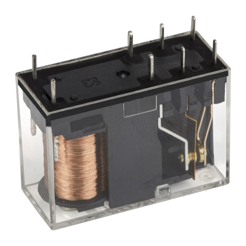
Inside a cabinet, format decisions usually matter more than small differences in contact material. Plug-in relays with transparent housings let a maintenance technician inspect contact condition, verify that the armature has dropped out, and replace a part without touching a soldered joint. DPDT configurations give two independent changeover circuits in one footprint, which is useful where a single relay must handle a control interlock and a signalling circuit at the same time.
Ningbo Helishun Electron builds general power relays in these formats, including transparent 8 pin DPDT types rated around 10 A and DPDT PCB types rated around 5 A for lower current duties. The transparent housing is not decoration. It shortens fault finding because a technician can see whether the contacts are pitted, whether the armature is free, and whether the relay is actually energised when the coil circuit says it should be.
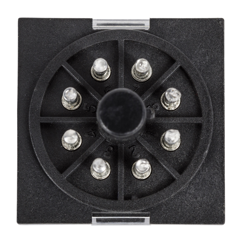 HLS-MK2P Transparent 8-Pin 10A DPDT Power RelayA transparent 8-pin DPDT relay rated 10A, suited to general power switching where visible contacts aid fault finding.View Product →
For embedded control boards, PCB pin relays make more sense than plug-in types, and the current rating can usually drop because the load is an on-board driver rather than a field actuator. A 5 A DPDT PCB relay covers a large share of interposing duties in instrumentation and appliance control boards, where the relay is switching a small valve, a lamp or a signal circuit rather than a motor.
 HLS-14F3L 5A DPDT PCB-Mount Power RelayAn 8-pin PCB relay rated 5A for interposing duties on instrumentation and appliance control boards, with Ag alloy contacts and TUV, CE and CQC listings.View Product →
Mounting orientation deserves a mention that many drawings ignore. Relay contacts are more reliable when the contact axis is vertical, so that any arcing debris falls away from the gap rather than settling across it. In a cabinet where relays are mounted horizontally for wiring convenience, the electrical life at higher loads can fall short of the datasheet curve. Where the layout cannot change, choosing a relay with a larger margin solves the problem more cheaply than reworking the plate.
Choose plug-in transparent housings where technicians need to see and replace parts quickly, and PCB types where the relay sits on a board and never needs to be touched.
Sockets Are Not Accessories; They Are Part of the Circuit
A relay socket adds two contact interfaces, a plastic body and a set of spring contacts to the circuit, and every one of those contributes resistance, heat and a possible failure point. Sockets are often specified last, after the relay has been chosen, and that is precisely backwards. The socket's current rating, terminal style and retaining method should be confirmed alongside the relay, because a socket rated at 10 A used with a 10 A relay leaves no margin at all.
Contact resistance in the socket is small but not zero, and it grows with thermal cycling and with contamination in a workshop environment. In a panel switching a 10 A load regularly, a socket that has loosened slightly will run warm, and warm spring contacts lose tension faster. Retaining clips exist for a reason: they keep the relay seated when a panel door is slammed or when a machine vibrates, and a relay that lifts a fraction of a millimetre can arc at the pin and fail in a way no datasheet predicts.
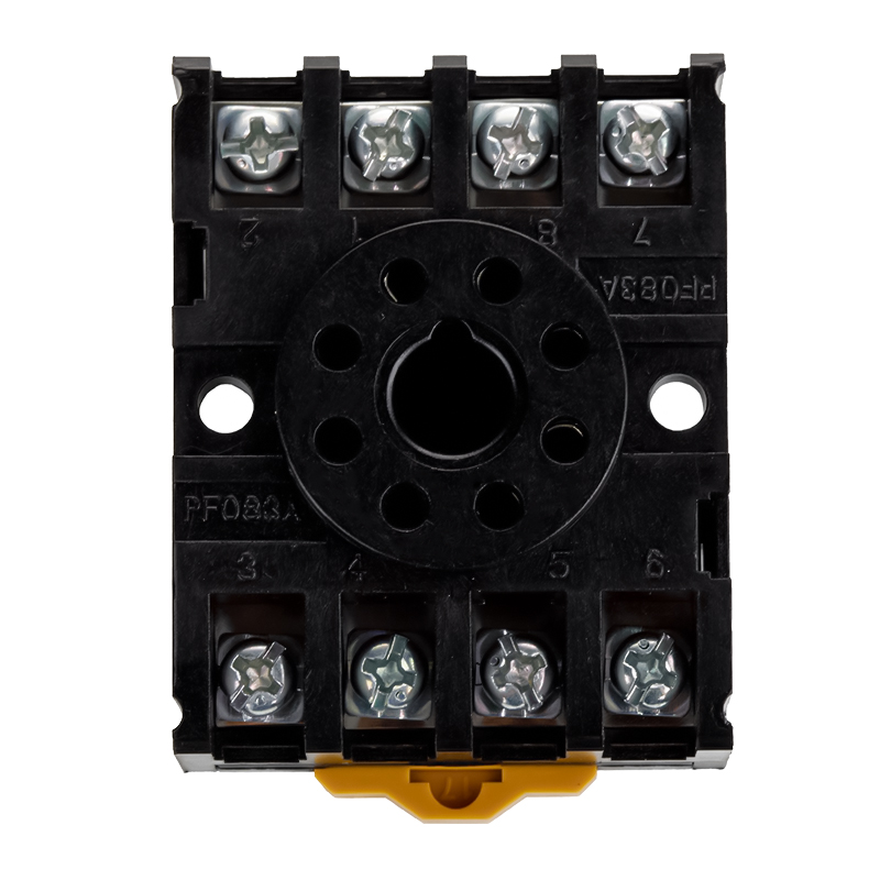 HLS-PF083A Relay Socket for MK2P RelaysAn OEM relay socket matched to MK2P relays, intended to keep relay and socket compatibility within a single supply chain.View Product →
Helishun's socket range covers 8, 11 and 14 pin relay families, including sockets for 13F, 4453 and MK2P/MK3P series, which keeps the relay and socket pair within one supply chain. That matters for procurement as much as for engineering. When relay and socket come from the same manufacturer, the mechanical tolerances were designed together, the current ratings are consistent, and a warranty question does not disappear into a gap between two suppliers.
DIN rail mounting, finger safe terminals, wire gauge and tightening torque all belong on the checklist. A socket that accepts 1.5 square millimetre wire comfortably will be easier to wire correctly than one that barely accepts it, and a terminal that needs a torque value printed on the side is a terminal that will be over tightened on a Friday afternoon. Labelling each socket position with the relay tag, the coil voltage and the contact duty pays for itself the first time a technician has to replace a part at two in the morning.
Match socket rating to relay rating with a margin, fit the retaining clip and label the position, because the cheapest component in the panel causes a disproportionate share of stoppages.
Wiring, Marking and Panel Layout Practice
Good panel practice around a safety monitoring relay is mostly about making faults visible and making maintenance possible. Safety channel terminals should be grouped and marked so that a technician cannot mistake them for standard control terminals. Wire colours should follow the site standard consistently, and the drawing should show the actual terminal numbers rather than a generic block.
- Keep safety channel wiring in its own duct, separated from motor and drive cables by at least the distance your EMC plan specifies.
- Use ferrules on every stranded conductor, sized to the terminal, and check the crimp rather than assuming it.
- Bring the feedback loop wiring back to the module on a dedicated pair, not shared with a coil return.
- Mark relay coils with the voltage and function, not only the tag number, so a replacement part is chosen correctly.
- Leave a service loop at plug-in relay positions so the socket can be replaced without re terminating the whole block.
- Record measured response times on the first build and keep them with the technical file for later comparison.
Layout also affects thermal performance. A row of relays crowded against a warm transformer will run hotter than the same relays on an open plate, and the derating curve in the datasheet assumes a specific mounting distance. Spacing relays apart, keeping power components below them where heat rises, and providing ventilation at the top of the enclosure are unglamorous measures that quietly extend contact life.
Documentation closes the loop. A short commissioning record listing the module type, the output device, the measured drop-out time, the coil voltages and the certificate numbers takes half an hour to write and saves days during an audit or a warranty dispute. Buyers who ask a supplier for certificate copies, batch markings and dimensional drawings at the quotation stage usually find that the same supplier is easier to work with during a technical query later.
Separation, labelling and a written commissioning record cost almost nothing and prevent most of the faults that appear in the first year of operation.
Choosing a Relay Manufacturer for Safety-Related Control Circuits
The commercial question is not only who can supply a relay, but who can supply the same relay next year with the same contact behaviour. Batch to batch variation in release time, contact resistance or spring tension will show up first in the safety related circuits, because those circuits are the least tolerant of drift. That is why the supplier's quality system and certification record belong in the selection process alongside the sample test.
Ningbo Helishun Electron has manufactured relays since 2000 from a facility of roughly 8,800 square metres in Ningbo, with products carrying UL, TUV, CE, CQC and RoHS compliance and a quality system certified to ISO 9001:2015. The company reports sales into more than one hundred countries, maintains offices in Guangzhou and Shenzhen, and has exhibited at the Munich electronics trade fair since 2004. For a buyer, those facts are a reasonable proxy for continuity of supply, though they should still be paired with a sample evaluation and a written specification.
OEM and ODM cooperation is worth raising early. Many panel builders reach a point where the standard catalogue part fits the electrical requirement but not the mechanical one, or where a private label marking is needed for a distributor's own range. Discussing that at the inquiry stage avoids a second round of tooling and documentation later. A relay manufacturer that already runs custom marking and modified terminal arrangements can usually shorten the path from prototype to series production considerably.
Supplier comparison should include a few questions that separate a component vendor from a manufacturing partner: can you provide dimensional drawings in editable format, can you confirm must-operate and must-release voltages, can you state the utilisation category at the current we actually switch, and can you hold a batch sample for traceability. A supplier that answers these clearly is usually also the one that responds quickly when a line is down.
Judge a relay manufacturer on documentation, certificate continuity and willingness to answer electrical questions in writing, not only on the unit price.
Procurement Details That Affect the Project Schedule
On the purchasing side, the details that derail projects are rarely dramatic. They are minimum order quantities that do not match a prototype run, lead times that assume a stock item which is actually made to order, and packaging that arrives without batch identification. A distributor or wholesaler buying for resale has the same problem in a different form: if the carton cannot be traced to a production lot, a customer complaint becomes very difficult to answer.
- Confirm the minimum order quantity for the exact variant, not the family, since coil voltage and contact arrangement change the part number.
- Ask for a sample of the production variant with the certificate copy and the dimensional drawing attached.
- Agree the marking on the relay and the carton, including the batch reference, before the first shipment.
- Check whether the socket is stocked at the same time, so that a relay order does not arrive without its mating part.
- Ask how a change of contact material or internal part would be communicated, and get that in writing.
- Keep one retained sample per batch for the first year, especially for safety related positions.
Price comparison deserves a fair basis. Two quotations for the same nominal relay can differ because one includes gold plated contacts, a higher temperature coil wire or a tighter release time window. Reducing the comparison to a single number invites a substitution later, and substitutions in safety related circuits are exactly the changes that invalidate a validation file.
Lead time planning should also account for the certification side. If a machine is exported to a market requiring UL or TUV evidence, the certificate must match the exact variant being fitted. A certificate for the family is not automatically a certificate for the coil voltage you ordered. Confirming this at the quotation stage avoids a shipment being held at the border for paperwork rather than for hardware.
Buy the exact variant, not the family, and confirm certificate coverage, marking and batch traceability before the first order is placed.
Ten Field Faults and the Habit That Prevents Each One
These are the faults that come up repeatedly when panels built around safety monitoring relays reach the field. None of them is exotic, and all of them are preventable with a checklist applied at design review rather than at commissioning.
- Feedback loop trips at random: the downstream contactor's auxiliary contact is not a mirror contact, or its release time exceeds the monitoring window.
- Relay welds after a few months: the contact was selected at 100 percent of a resistive rating for an inductive load.
- Relay chatters during motor starting: control transformer cannot supply simultaneous coil inrush and the supply sags.
- Slow drop-out after a stop command: flyback diodes were added to the output relay coils for driver protection.
- Intermittent start inhibition: both safety channels share a multicore cable and pick up a cross fault.
- Socket overheating: socket rating matched the relay exactly, with no allowance for ambient temperature.
- Relay lifts in service: retaining clip omitted during a field replacement.
- False trips on a light curtain: interface not rated for the test pulse width used by the controller.
- Contact film on signal circuits: standard silver contacts used for a dry circuit at very low current.
- Audit finding: no record of measured response time, no retained batch sample, certificate matching a different variant.
Each of these faults has a cheap prevention and an expensive cure. The preventive version usually involves a question asked before the order is released, which is why the specification stage matters far more than the troubleshooting stage.
Nearly every field fault on this list traces back to a specification shortcut taken weeks earlier, so spend the time at design review instead of at commissioning.
Frequently Asked Questions About Safety Monitoring Relays
Is a safety monitoring relay the same thing as a general power relay?
No. A safety monitoring relay contains redundant input channels, internal diagnostics and defined fault behaviour, and it is certified against functional safety standards. A general power relay, including the types used in panel auxiliary circuits, switches a load on command without those guarantees. The two work together in a machine, but they are not interchangeable and should never be substituted for one another on the strength of a similar footprint.
How do I choose between a dedicated safety relay module and a safety controller?
Count the safety functions first. A machine with one or two guarded doors and a single emergency stop is usually served well by a compact module, which is simpler to wire and easier to diagnose with a meter. When the same machine needs several zones, muting, or configuration that changes between product variants, a controller or a safety network usually pays for itself in wiring and changeover time.
What response time should I ask a supplier for?
Ask for the value measured on the specific output type you are buying, then add the release time of the downstream contactor and the machine's own stopping time. The total, not the module figure, determines the required safety distance. A written figure for release at 80 percent of nominal coil voltage is more useful than a single nominal value.
Only with the same care you would apply to any other component in the chain. The socket must carry the current with margin over the ambient temperature, hold the relay firmly, and be traceable. Where the socket sits in the output path, its condition affects the response time, so inspect and replace it on a defined interval rather than waiting for a fault.
Why does a diode across a coil change my stopping time?
A flyback diode gives the collapsing coil current a low resistance path, which slows the decay of the magnetic field and therefore delays the release of the armature. The difference can be significant compared with an unsuppressed coil. If drop-out time sits inside a safety calculation, use an RC network or a varistor and verify the resulting release time by measurement.
What certifications should a relay manufacturer hold for export projects?
At minimum, look for evidence matching the destination market and the exact variant: UL and CQC are common baselines, TUV and CE cover European requirements, and RoHS compliance is expected for electronics entering the EU. A quality system certificate such as ISO 9001:2015 supports consistency, but the product certificate still has to name the variant you are fitting.
How many samples should I evaluate before approving a supplier?
Enough to see variation, not just to see one good unit. A practical approach is three batches if available, with measurements of pick-up voltage, release voltage, release time and contact resistance recorded for each. If three batches behave consistently, batch to batch drift is less likely to surprise you in production.
Can one relay serve two safety channels?
Generally no. Using a single relay to switch both channels of a safety function removes the redundancy that the architecture depends on. Where a compact design needs two outputs, specify a relay with two independent contact sets and separate the channels in wiring as well, so that a single fault cannot bridge them.
Most buying mistakes around safety monitoring relays come from treating the module as the whole system and the relay, socket and wiring as an afterthought.
Where to Go Next
If you are at the specification stage, the most useful next step is a short internal review: list every relay position in the safety chain, note the actual load, the ambient temperature, the supply tolerance and the required release time, and compare that list with the datasheets you have. Gaps in the list tell you exactly which questions to send to a supplier.
Reference pages for this topic
Whether you are a panel builder, an equipment manufacturer or a wholesaler sourcing for resale, the same rule holds: the relay that carries the load and the socket it sits in are not commodities to be swapped at the last minute. They are the parts that decide whether the safety monitoring relay you paid for actually delivers the stopping performance written in your technical file.
Specify the whole chain, measure it once, and keep the record; that is what turns a certified module into a machine that passes validation and stays in production.


