



 English
 中文简体
Content
- 1 Relay Terminal Numbers Are Function Labels, Not Pin Positions
- 2 What 30, 85, 86 and 87 Do in a Four-Pin Relay
- 3 When Terminal 87a Turns a Four-Pin Relay into a Changeover Relay
- 4 Terminal 31, 15, 50 and Other Numbers You May See
- 5 PCB Relay Pin Numbers vs Automotive Terminal Numbers
- 6 How Relay Sockets Change the Numbering Conversation
- 7 Reading a Relay Datasheet Without Mixing Up Coil and Contact Pins
- 8 A Practical Buyer's Checklist for Relay Terminal Numbers
- 9 Compatibility, Replacement and the “Same Layout” Claim
- 10 Common Wiring Mistakes That Start with a Wrong Terminal Number
- 11 Terminal Numbers and Certification: What They Do Not Tell You
- 12 FAQ About Relay Terminal Numbers
- 12.1 What do relay terminal numbers 30, 85, 86, 87 and 87a mean?
- 12.2 Are relay terminal numbers the same on all relays?
- 12.3 What is the difference between 4-pin and 5-pin relay terminal numbers?
- 12.4 Is terminal 87a a ground?
- 12.5 Can I use a 5-pin relay in place of a 4-pin relay?
- 12.6 How do I test relay terminal numbers with a multimeter?
- 12.7 Why does my relay have two 87 terminals?
- 12.8 What do A1 and A2 mean on a relay?
- 12.9 Do PCB relay pin numbers match automotive terminal numbers?
- 12.10 How do I choose a relay supplier for terminal-number-compatible replacements?
- 13 Make Terminal Numbers Part of Your Approval Drawing
A maintenance engineer opens a panel and finds a five-pin cube relay marked with the numbers 30, 85, 86, 87 and 87a. The wiring diagram is missing, the replacement relay is in a drawer, and the machine is down. The fastest way to get it wrong is to assume those numbers describe pin positions in a simple sequence. They do not. Relay terminal numbers are function codes. They tell you which terminal belongs to the coil, which one carries the battery feed, and which one switches the load. Once you read them as functions rather than positions, a four-pin relay, a five-pin changeover relay and a relay socket all become easier to compare.
This guide is written for buyers, design engineers, maintenance teams and wholesale sourcing staff who need to specify or replace relays without guessing. It explains the common DIN 72552 terminal numbers, the difference between four-pin and five-pin relay terminal numbers, the way PCB relays use pin numbers differently, and the checks that matter when you buy from a relay manufacturer or supplier. The short version is simple: match the function, the footprint and the rating together. A number alone is not enough.
Treat relay terminal numbers as a function map, not a pin count, and confirm the map against the datasheet, the socket and a sample before approval.
Relay Terminal Numbers Are Function Labels, Not Pin Positions
The numbers 30, 85, 86, 87 and 87a come from the German DIN 72552 standard for vehicle electrical systems. The standard assigns each number a circuit role. Terminal 30 is normally the battery positive feed, 31 is the ground return, 85 and 86 are the two ends of the coil, 87 is a normally open contact, and 87a is a normally closed contact. That is why a relay can carry the same five numbers in a different physical order and still work in the same circuit. The numbers describe what the terminal does, not where it sits on the body.
This distinction matters during replacement. A purchasing team may compare two five-pin relays and see the same numbers on both cases. That does not prove they are interchangeable. The terminal positions, the terminal width, the coil voltage, the contact material and the suppression circuit can all differ. A relay with the same numbers but a built-in diode may fail if the coil polarity is reversed. A relay with a lower 87a rating may work in a test bench and fail in a door lock or changeover circuit. The number tells you the intended role. The datasheet tells you whether the part can carry that role in your application.
For automotive relay pin numbers, the common set is small, but the physical layouts are not. ISO mini relays and ISO 280 style relays use similar function codes in different bodies. Some relays have two 87 terminals for the same normally open contact, which helps current sharing and wiring convenience. Some sockets repeat numbers by pole for multi-pole relays. Some PCB relays abandon DIN numbers entirely and print pin 1, pin 2 and so on. A buyer who reads only the number and ignores the drawing is taking a avoidable risk.
| Terminal number | Typical function | What it connects to | Buyer check |
|---|---|---|---|
| 30 | Battery positive input | Fused supply to the load contact | Fuse rating, terminal width, continuous current |
| 31 | Ground return | Chassis or DC negative | Return current path, corrosion protection |
| 85 | Coil negative | Control ground or switch | Coil voltage, suppression diode polarity |
| 86 | Coil positive | Control positive | Must-operate voltage, coil resistance |
| 87 | Normally open contact | Load when the relay is energized | Load type, inrush current, derating |
| 87a | Normally closed contact | Load when the relay is de-energized | Rating of the closed contact, changeover use |
| 15 | Ignition-switched positive | Vehicle ignition bus | Whether the coil should be live with key on |
| 50 | Starter control | Starter solenoid signal | Control-only use, not a load contact |
Table 1 is a starting point, not a universal wiring law. The same number can appear on a relay, a socket, a fuse box and a vehicle harness. In a sourcing discussion, ask for a terminal map that shows the numbers, the physical positions and the contact form on one drawing. That single document prevents most of the confusion that surrounds 4-pin relay terminal numbers and 5-pin relay terminal numbers.
A terminal number tells you what the pin is supposed to do; the drawing and the datasheet tell you whether the relay will fit and survive.
What 30, 85, 86 and 87 Do in a Four-Pin Relay
A four-pin relay is usually a single normally open switch with an electromagnet coil. Terminal 30 is the common contact and normally receives the fused supply. Terminal 87 is the normally open contact and feeds the load when the coil is energized. Terminals 85 and 86 form the coil circuit. In many automotive relays, 85 is connected to ground and 86 receives the control positive from a switch. Some relays are polarity-sensitive because a suppression diode or resistor is fitted across the coil. Others are non-polarized. You cannot tell by looking at the outside alone.
The practical test is straightforward. With the relay removed and the coil unpowered, an ohmmeter across 85 and 86 should show a coil resistance, not an open circuit and not a short. Across 30 and 87, the meter should show an open circuit. When the correct coil voltage is applied, the contact should close and the resistance between 30 and 87 should drop to a low value. A five-pin relay adds 87a, so the same test should show continuity between 30 and 87a when the coil is off, and continuity between 30 and 87 when the coil is on. These checks do not prove the contact rating or the service life, but they catch a wrong terminal map quickly.
For a four-pin 30A automotive relay with quick-connect pins, the HLS4121 is one option in the Helishun range. It is the kind of part a maintenance team might use for a fan, horn, lamp or accessory circuit where a single normally open contact is enough. The important buying question is not only whether it has 30, 85, 86 and 87. It is whether the terminal width matches the harness, whether the coil is suitable for 12V or 24V, and whether the contact is rated for the inductive or capacitive load in the application.
 HLS4121 4-Pin 30A Automotive Relay with Quick-Connect PinsReview this 30A four-pin relay when matching quick-connect terminals, 12V or 24V coil options, and contact ratings to fan, horn, lamp, or accessory loads.View Product →
Wire gauge deserves more attention than it often gets. The coil current is small, maybe a fraction of an amp, so 85 and 86 can use thin control wire. The load current through 30 and 87 can be tens of amps, and that current must be carried by the terminals, the PCB traces or the socket contacts. A relay rated at 30A will not fix a harness with undersized wire or a socket with poor contact pressure. Put the fuse on the supply side of terminal 30, and keep the load return path short and solid.
Another common error is to use the relay as a polarity device. A four-pin normally open relay does not reverse polarity. It switches one path on and off. If a motor must run forward and reverse, you need a changeover arrangement or an H-bridge, not a single 30 and 87 contact. If a lamp must be on when the ignition is off and off when the ignition is on, a normally closed contact is the function you need, which leads to terminal 87a.
On a four-pin relay, 30 and 87 are the load path, while 85 and 86 are the control path; mixing those two paths is the fastest way to damage a contact or a coil.
When Terminal 87a Turns a Four-Pin Relay into a Changeover Relay
A five-pin relay usually adds terminal 87a to the four-pin layout. In the de-energized state, terminal 30 connects to 87a. When the coil is energized, terminal 30 breaks from 87a and connects to 87. This is a single-pole double-throw arrangement, often shortened to SPDT. It is useful when one supply must feed one of two loads, or when a circuit must default to one path and switch to another when a control signal appears. It is not a second battery feed and it is not a ground terminal.
The most common mistake with terminal 87a is to treat it as a convenient ground. It is a switched contact. If 87a is connected to ground and the relay energizes, the contact can connect the supply on 30 to ground through the load or through a short path. The result can be a blown fuse, a damaged contact or a failed control module. Read 87a as a normally closed output. It has its own current limit, and on some relays that limit is lower than the normally open 87 contact. If the circuit needs equal current in both states, check the datasheet rather than assuming the two contacts are symmetrical.
Changeover relays are common in automotive body control, lighting selection, accessory switching and alarm circuits. They also appear in industrial control panels where a relay selects between a main sensor and a backup sensor. In those cases, the buyer needs to know the contact form, the coil voltage, the terminal arrangement and the socket. A five-pin relay with a nice-looking terminal map can still be the wrong part if the 87a contact is only rated for a small signal load and the application draws a motor current.
For higher load switching in a five-pin automotive body, the HLSCMA3 is a 5-pin 40A relay with PCB or quick-connect pin options in the Helishun range. It illustrates why terminal numbers and current ratings must be read together. The presence of 87a does not mean the relay is suitable for any changeover job. The contact rating, the expected inrush current and the number of operations all shape the selection.
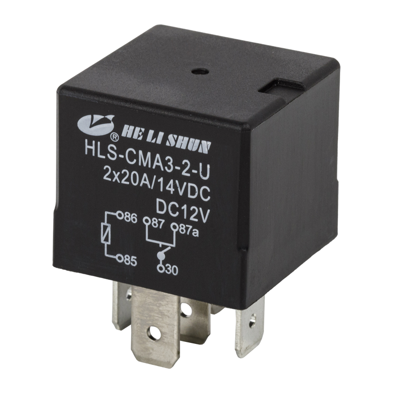 HLSCMA3 5-Pin 40A Automotive Relay for Higher Load SwitchingCheck this 40A five-pin relay when evaluating 87a changeover contacts, PCB or quick-connect mounting, and contact ratings against inrush and operation counts.View Product →
When replacing a four-pin relay with a five-pin relay, do not assume the extra terminal can be left floating in every socket. In some sockets, the 87a position is already connected to a circuit. In others, the physical keying prevents a five-pin relay from seating in a four-pin socket. If the socket accepts both, trace the 87a contact before powering the circuit. A changeover relay used in a normally open application can be fine, but only when the unused contact is treated as an unused contact, not as a spare ground.
Terminal 87a is a normally closed switched contact with its own rating, so never use it as a ground or as an unrestricted second supply.
Terminal 31, 15, 50 and Other Numbers You May See
Automotive wiring uses more DIN 72552 numbers than the five that appear on a cube relay. Terminal 31 is the ground return. Terminal 15 is the ignition-switched positive. Terminal 50 is the starter control signal. These numbers may appear on a relay socket, a fuse box or a harness label rather than on the relay itself. They are useful because they tell a technician what kind of signal is expected. Terminal 15 should not be treated as a permanent battery feed. Terminal 50 should not be used to power a heavy load. The number is a circuit identity, not a suggestion that any nearby relay can switch it.
Some relays carry two 87 terminals. Both are normally open contacts and both are connected to the same internal contact bridge. They exist to simplify wiring or to share current across two terminal blades. If a drawing shows 87 and 87 on the same relay, do not read the second one as 87a. The second 87 is still a normally open output. The changeover contact is 87a, and the two are not interchangeable. This is one of the most common points of confusion in automotive relay pin numbers because the numbers look similar at a glance.
Industrial relays often use a different marking system. Under IEC conventions, the coil may be marked A1 and A2, while contacts use two-digit numbers such as 11, 12 and 14 for a normally closed and normally open contact pair. A second pole might use 21, 22 and 24. These markings are not the same language as DIN 72552. An 8-pin industrial relay may have A1 and A2 for the coil and 11, 12, 14, 21, 22 and 24 for two changeover contacts. A buyer who tries to map those numbers directly to 30, 85, 86 and 87 will create a wrong cross-reference.
This is why a relay datasheet should be read as a whole. The terminal map, the schematic and the physical drawing must agree. If a supplier offers a replacement and only quotes “same as original” without a terminal drawing, ask for the drawing. If the drawing shows a different contact form, a different coil polarity or a different terminal width, the replacement is not a drop-in part even if the case looks similar. The cost of a wrong assumption is usually higher than the cost of a sample test.
Not every number on a relay belongs to the same standard, so separate the automotive DIN codes from industrial IEC markings before you build a cross-reference.
PCB Relay Pin Numbers vs Automotive Terminal Numbers
A PCB relay often has a row of pins numbered 1, 2, 3, 4 and so on. Those numbers usually identify the pin position on the package, not the electrical function. Two different 8-pin PCB relays can use pin 1 and pin 2 for the coil on one model and pin 1 and pin 8 on another. The same printed number may mean coil on one relay and common contact on another. For a PCB relay, the datasheet is the map. The case marking is only a reference to that map.
This difference is important for buyers who are used to automotive relay terminal numbers. A 5-pin PCB relay may look like a cube relay, but its pin numbering may follow a manufacturer-specific footprint. The coil pins may be at one end, the common contact in the middle and the normally open and normally closed contacts at the other end. If the PCB footprint is already fixed, the replacement must match the hole pattern, the pin diameter, the pin length and the internal connection. A relay with the right electrical ratings but the wrong pin map will not fit the board without a redesign.
For an 8-pin DPDT 5A PCB relay, the HLS14F3L is one example in the Helishun general power relay range. It shows why a buyer should ask for a pin drawing rather than a pin count alone. The relay has two changeover contacts, a coil and a specific footprint. The datasheet must show which pin is the coil, which pins are the commons, and which pins are the normally open and normally closed contacts. That information is more useful than a generic statement that the relay is “8-pin”.
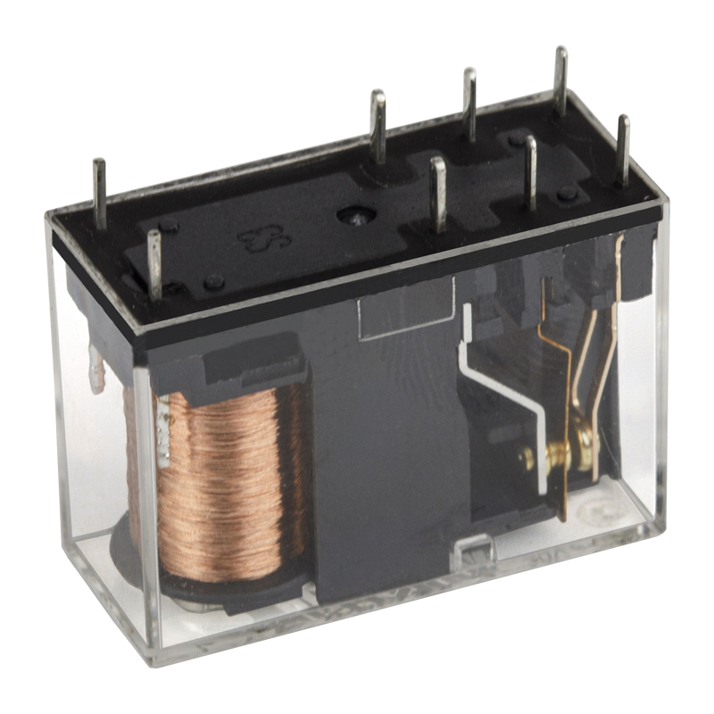 HLS14F3L 8-Pin DPDT 5A PCB Power RelayAsk for the pin drawing when reviewing this 8-pin DPDT relay, so coil, commons, normally open, and normally closed contacts match the PCB footprint.View Product →
PCB relay pin numbering also affects test fixtures and production programming. If the relay is socket-mounted, the socket may translate the PCB pin numbers into screw terminal numbers. If the relay is soldered directly, the board silkscreen must match the relay drawing. A mismatch can put coil voltage across a contact or short two supply rails. The risk is higher in low-volume builds where the relay is second-sourced without a full drawing review.
The practical rule is to keep two documents side by side: the relay datasheet and the socket or PCB footprint drawing. Mark the coil pins, the common pins and the contact pins on both. If the pin numbers differ but the functions line up, the relay may still be electrically suitable for a redesign. If the functions do not line up, the number is irrelevant. The function is the thing that must match.
On a PCB relay, the printed numbers are package references; only the datasheet can tell you which pin is the coil and which pin is the contact.
How Relay Sockets Change the Numbering Conversation
Relay sockets add another layer because they have their own terminal numbers, screw markings or clamp labels. An 8-pin socket for a 13F1 or 13F2 relay may use a terminal layout that follows the relay pin positions. An 11-pin socket for a 13F3 relay and a 14-pin socket for a 13F4 relay each have a different physical arrangement. Sockets for MK2P and MK3P relays follow their own patterns. The socket number may correspond to the relay pin number, but it may also be a socket terminal identifier that only makes sense with the socket drawing.
This is why relay socket terminal numbers should be checked separately from relay terminal numbers. A socket may be rated for 5A while the relay is rated for 10A. The relay contact may be fine, but the socket terminal, spring or screw clamp becomes the weak point. A socket may also have a different creepage distance, a different wire range or a different retaining clip. In a control cabinet, these details affect installation time and long-term reliability. In a vehicle, vibration and temperature cycling make them even more important.
Helishun produces sockets for several relay families, including sockets for 13F1 and 13F2 relays, a socket for 13F3, a socket for 13F4, sockets for the 4453 series, and sockets for MK2P and MK3P relays. For a buyer, the useful question is not only “which socket fits this relay” but “which socket, relay and terminal map have been tested together”. A socket that fits mechanically but reverses the coil and contact terminals is worse than no socket at all. A socket with the correct pinout but a lower current rating is a hidden bottleneck.
When a machine is being repaired, the existing socket may be worn, discolored or cracked. Replacing only the relay can restore operation for a short time, but a damaged socket can overheat a new relay. Check the terminal clamping force, the wire insulation, the presence of a retaining clip and the signs of arcing. If the socket terminal numbers are faded, use the socket drawing rather than guessing from the relay. The socket is part of the circuit, and its numbering is part of the installation.
A correct relay in a mismatched or under-rated socket is still a wrong installation, so approve the relay and socket as one assembly.
Reading a Relay Datasheet Without Mixing Up Coil and Contact Pins
A relay datasheet should answer four questions before it talks about price. First, what is the coil voltage and coil resistance? Second, what is the contact form and how many poles? Third, what are the contact ratings for resistive, inductive and motor loads? Fourth, what is the terminal arrangement and physical footprint? If any of those four is missing, the datasheet is not ready for a sourcing decision. A terminal number without a rating is only half the information.
Coil data deserves a careful read because it affects both the control circuit and the heat inside the relay. A 12V coil with a low resistance draws more current and runs warmer than a high-resistance coil. The must-operate voltage and must-release voltage tell you whether the relay will drop out cleanly when the supply sags. The coil suppression method matters too. A diode across 85 and 86 protects the driving transistor, but it also makes the coil polarity-sensitive and can increase release time. A resistor or varistor has different trade-offs. If the replacement relay has a different suppression method, the control circuit may behave differently even though the terminal numbers are the same.
Contact data needs the same discipline. A relay marked 30A may be rated for 30A on a resistive load at a specific temperature and duty cycle. An inductive load such as a motor, solenoid or compressor can draw a high inrush current and produce an arc when it opens. The same relay may need derating for that load. A 5-pin relay with 87a may have a lower rating on the normally closed contact than on the normally open contact. If the application uses 87a for a lamp or a small solenoid, that may be acceptable. If it uses 87a for a motor, the buyer needs the motor-load rating, not just the general contact rating.
Mechanical and electrical life also belong in the comparison. A relay that switches once a day has a different duty from a relay that switches every few seconds. The number of operations, the ambient temperature and the load type all affect service life. A supplier may quote a mechanical life of millions of operations, but the electrical life under load can be much lower. For a relay manufacturer, the useful discussion is about the actual load profile, not only the terminal numbers. For a buyer, that discussion is how you avoid a part that works on the bench and fails in the field.
Finally, check the drawings for terminal width, pin length, recommended PCB hole size and socket compatibility. A 6.3mm quick-connect terminal and a 4.8mm terminal are not interchangeable without an adapter. A PCB relay with the same pin count but a different pin length may not reach the solder joint properly. These details are not glamorous, but they are the difference between a first-time fit and a line stoppage.
A terminal number is a location; a rating is a promise under stated conditions, and a buyer needs both on the same approved drawing.
A Practical Buyer's Checklist for Relay Terminal Numbers
The checklist below is written for a sourcing team that needs to compare a replacement relay with an existing part. It works for a maintenance spare, a new product design and a wholesale order. The goal is to turn a vague “same pinout” claim into a set of verifiable facts.
- Confirm the relay family and pin count. Decide whether the part is a four-pin normally open relay, a five-pin changeover relay, an eight-pin dual-pole relay or another arrangement. Do not start with the terminal numbers alone.
- Photograph the existing relay, the socket and the wiring before removal. Record the terminal numbers, the wire colors and the physical positions. A photograph is often the fastest way to catch a reversed 85 and 86 connection.
- Obtain the datasheet drawing. The drawing should show the terminal numbers, the contact schematic and the physical dimensions on one page. If the supplier cannot provide it, treat the part as unverified.
- Identify the coil pins with an ohmmeter. On a DIN-style relay, 85 and 86 should show a coil resistance. On a PCB relay, use the datasheet because the printed numbers may not follow DIN. A short or open reading is a reject.
- Check the load path. Confirm that 30 is the common contact and 87 is the normally open contact. If the circuit uses 87a, confirm that the normally closed contact is rated for the load and that it is not being used as a ground.
- Check the terminal width and plating. A 4.8mm terminal will not reliably mate with a 6.3mm quick-connect receptacle. Tin plating, silver plating and contact material can affect life and contact resistance.
- Check the socket rating. The socket must match the relay pinout and carry the load current. Look for signs of overheating, loose clamps or cracked insulation in existing sockets.
- Check the coil suppression. If the relay has a built-in diode, confirm the polarity of 85 and 86. If the original relay used a resistor or varistor, a diode replacement may change release time or interference behavior.
- Check certification and scope. Ask for the UL, TUV, CQC or RoHS documentation that applies to the exact model. A certificate for a family does not automatically cover every terminal variant or contact rating.
- Run a sample test. Verify coil operation, contact continuity, insulation resistance and temperature rise under the intended load. For a new design, test the relay and socket together, not separately.
The checklist is deliberately repetitive. Each item catches a different failure mode. A relay can have the correct terminal numbers and the wrong terminal positions. It can have the correct positions and the wrong coil voltage. It can have the correct coil and a contact rating that is too low for an inductive load. The only way to reduce the risk is to check the function, the footprint, the rating and the certification as separate facts.
For wholesale sourcing, add one more step: document the approved alternate. If the buyer approves a second source, the approval should include the terminal map, the datasheet revision and a sample reference. That record prevents a later shipment from arriving with a “same” relay that has a different 87a contact or a reversed coil polarity.
Approve a relay only after the terminal map, footprint, contact rating, coil data and certification have been checked as one package.
Compatibility, Replacement and the “Same Layout” Claim
Many buyers search for a relay that can replace an existing part without changing the harness or the PCB. Helishun describes its product characteristics and installation layouts as consistent with comparable international products, and positions its relays as a replacement option. That is useful for sourcing, but it should be read carefully. “Same layout” should mean the terminal numbers, the physical positions, the terminal width, the coil voltage and the contact form all line up. It should not mean only that the case looks similar.
When a replacement is proposed, ask for a side-by-side drawing. Mark terminal 30, 85, 86, 87 and 87a on both parts. Check the terminal positions from the bottom view and the side view. Check the height, the mounting ear and the retaining clip. Check whether the original relay has a suppression diode and whether the replacement has the same suppression. A relay that is electrically compatible but mechanically taller may not fit under a cover. A relay that fits mechanically but has a different 87a rating may pass a bench test and fail in service.
OEM and ODM projects need the same discipline at an earlier stage. Helishun welcomes OEM and ODM cooperation, which means a customer may bring a drawing, a sample or a performance requirement. The best starting point is a terminal map and a test plan. The terminal map defines the function of each pin. The test plan defines the coil voltage, the load profile, the operating temperature and the acceptance criteria. With those two documents, a manufacturer can propose a standard relay or a customized variant without ambiguity.
For a distributor or wholesaler, compatibility also has a commercial dimension. A part that is marketed as a replacement should be easy to identify in a catalog. The catalog entry should show the terminal numbers, the contact form, the coil voltage, the current rating and the socket family. If the catalog only shows a photo, the buyer cannot compare it with the original. Good product data reduces returns and technical support calls.
A replacement claim is only useful when it is backed by a side-by-side terminal drawing, a matching footprint and a verified contact rating.
Common Wiring Mistakes That Start with a Wrong Terminal Number
Most relay failures that look like product failures are actually wiring failures. The terminal numbers are correct on the relay, but the wires are connected to the wrong function. The following mistakes appear often in maintenance reports and field returns.
- Putting the battery positive on 87a instead of 30. The load may work only when the relay is off, or it may be permanently live. In a changeover circuit, this reverses the intended default state.
- Using 87a as a ground. This can create a short when the relay energizes. The contact is a switch, not a return path.
- Reversing 85 and 86 on a relay with a built-in diode. The diode can conduct in the wrong direction, blow the control fuse or damage the driving transistor.
- Leaving out the flyback protection on a bare coil. The voltage spike can damage a control module even if the relay itself survives. If the relay has built-in suppression, confirm the polarity before wiring.
- Feeding the coil from the load side of the relay. The relay can chatter or fail to pull in because the coil voltage disappears when the contact opens.
- Using a five-pin relay in a four-pin socket without checking the 87a position. The extra terminal may touch a live circuit or remain unconnected in a way that changes the default state.
- Omitting the fuse on terminal 30. The relay contact is not a current-limiting device. A short on the load side will damage the relay, the socket or the harness.
- Mixing terminal width. A 6.3mm receptacle on a 4.8mm relay terminal can feel tight but make poor contact. The result is heat, intermittent operation and a misleading “bad relay” diagnosis.
Each mistake is easy to prevent with a labeled harness and a terminal map. During installation, mark the relay side and the harness side. After installation, pull gently on each terminal to confirm engagement. Measure the coil voltage at 85 and 86 while the relay is energized. Measure the voltage drop across 30 and 87 under load. A high drop suggests a poor terminal, an undersized wire or a worn contact. These measurements take a few minutes and are more reliable than replacing parts by guesswork.
For a relay supplier, field returns often contain useful information. If the same terminal number fails repeatedly, the issue may be a load profile that exceeds the published rating. If the same socket shows heat marks, the issue may be the socket rather than the relay. A good supplier will ask for the terminal map, the load type and the measured current before concluding that the relay is defective.
Label the harness, verify the coil and load paths with a meter, and treat every unusual terminal connection as a potential short until proven otherwise.
Terminal Numbers and Certification: What They Do Not Tell You
Certification is important, but it does not replace the terminal map. A relay may carry UL, TUV, CQC or CE recognition and still be wired incorrectly. The certificate confirms that the product meets certain safety and performance requirements under defined conditions. It does not confirm that terminal 87a is the right contact for a motor load or that terminal 30 is fused correctly. Buyers should read the certificate scope, the model designation and the ratings, then compare them with the application.
Helishun states that its products have obtained UL, TUV, CE and CQC certification, comply with RoHS requirements and are produced under an ISO 9001 quality management system. The site also lists IECEx among its certifications. For a buyer, the useful step is to ask for the certificate that matches the exact model and the intended market. A certificate for a similar model is not the same as a certificate for the part on the purchase order. If the application is in an explosive atmosphere, the certification scope and the enclosure rating become especially important.
RoHS compliance is also worth checking at the part number level. A relay may be RoHS compliant in one plating option and not in another. The terminal plating, contact material and solderability can change with the finish. If the product is used in a PCB assembly, the solder profile and the maximum temperature should be confirmed with the datasheet. These details are not visible in a terminal number, but they affect the manufacturing yield.
For a maintenance replacement, certification is not a substitute for a sample test. The original relay may have been certified for a specific load, but the replacement may have a different contact material or a different internal construction. If the replacement carries the same terminal numbers and the same certification, that is a good start. It is not the whole approval. The final check is the performance in the actual circuit, with the actual load and the actual ambient temperature.
Certification supports a relay approval, but the terminal function, the load rating and the installation still have to be verified for the specific application.
FAQ About Relay Terminal Numbers
What do relay terminal numbers 30, 85, 86, 87 and 87a mean?
In the common DIN 72552 automotive scheme, 30 is the battery positive input, 85 and 86 are the coil terminals, 87 is the normally open contact and 87a is the normally closed contact. The numbers describe functions, not physical pin positions. Always confirm the layout on the relay drawing because the same numbers can appear in different positions on different bodies.
Are relay terminal numbers the same on all relays?
No. Automotive relays often follow DIN 72552, while industrial relays may use IEC markings such as A1 and A2 for the coil and 11, 12 and 14 for contacts. PCB relays may use simple pin numbers that are specific to the package. The same number can mean different things in different standards, so the datasheet is the final reference.
What is the difference between 4-pin and 5-pin relay terminal numbers?
A four-pin relay normally has 30, 85, 86 and 87, which gives one normally open contact. A five-pin relay adds 87a, which gives a normally closed contact and turns the relay into a changeover device. The five-pin relay can switch between two paths, but the 87a contact has its own rating and must not be treated as a ground.
Is terminal 87a a ground?
No. Terminal 87a is a normally closed switched contact. In the de-energized state, it connects to terminal 30. When the coil is energized, that connection opens and 30 connects to 87 instead. Using 87a as a ground can create a short circuit when the relay operates.
Can I use a 5-pin relay in place of a 4-pin relay?
Sometimes, but only if the socket and circuit are checked. A five-pin relay has an extra 87a terminal that may touch a live circuit in a four-pin socket. If the application only needs a normally open contact, the 87a terminal should be treated as unused and insulated or left unconnected according to the socket design. Verify the pin positions before installation.
How do I test relay terminal numbers with a multimeter?
With the relay off, measure the coil resistance across 85 and 86. Check that 30 and 87 are open. On a five-pin relay, check that 30 and 87a are closed. Apply the rated coil voltage and confirm that 30 and 87 close. These tests confirm the basic terminal map, but they do not confirm the contact rating or the service life.
Why does my relay have two 87 terminals?
Two 87 terminals are normally the same normally open contact brought out on two blades. They can simplify wiring or share current across two terminals. They are not 87a, and they do not provide a normally closed function. Check the internal schematic to confirm that the two 87 terminals are connected together.
What do A1 and A2 mean on a relay?
A1 and A2 are common IEC markings for the coil terminals on industrial relays. They are not the same as 85 and 86, although both pairs describe the coil. The contact markings in that system often use numbers such as 11, 12 and 14. Do not mix IEC and DIN markings in one cross-reference without a drawing.
Do PCB relay pin numbers match automotive terminal numbers?
Usually not. PCB relay numbers often identify package positions such as pin 1, pin 2 and pin 3. They do not automatically correspond to 30, 85, 86 and 87. The datasheet must show which pin is the coil, which pin is the common contact and which pins are the normally open and normally closed contacts.
How do I choose a relay supplier for terminal-number-compatible replacements?
Ask for a terminal drawing, a datasheet with ratings, a sample and the certificate that applies to the exact model. Compare the terminal positions, the footprint, the coil voltage, the contact form and the load rating. A supplier that can provide those documents is easier to qualify than one that only offers a photo and a pin count.
The safest sourcing rule is to match function, footprint, rating and certification, then verify the terminal map with a sample before production.
Make Terminal Numbers Part of Your Approval Drawing
Relay terminal numbers are simple once they are read as functions. Terminal 30 is the common supply, 85 and 86 are the coil, 87 is the normally open contact and 87a is the normally closed contact. The difficulty comes when those functions are mixed with pin positions, socket labels, PCB pin numbers or a different standard. A buyer who checks only the numbers on the case can miss a reversed coil, an under-rated 87a contact or a socket that cannot carry the load.
The better approach is to make the terminal map part of the approval drawing. Show the relay, the socket and the harness connection in one view. Mark the coil pins, the load path and the changeover contact. Add the coil voltage, the contact rating, the terminal width and the certification. Then test a sample in the intended circuit. That process is more reliable than a catalog photo, and it gives the maintenance team a document they can use during the next replacement.
For projects that need a standard relay or a customized variant, the conversation should start with the terminal map and the load profile. A relay manufacturer can then recommend a part that matches the function and the footprint, rather than a part that only looks similar. The same discipline helps distributors and wholesalers present clear product data and reduce technical support questions.
Explore Helishun
Put the terminal map on the approval drawing, test the relay and socket together, and keep the approved revision for every future order.


