



 English
 中文简体
Content
- 1 What On Delay Means on a Time Delay Relay
- 2 How an On-Delay Time Delay Relay Reaches Its Setpoint
- 3 Six Datasheet Numbers That Decide Whether an On-Delay Relay Fits
- 4 Coil Voltage, Contact Rating and the Load You Forgot to Count
- 5 Wiring an On Delay Relay: Sockets, DIN Rail and Common Mistakes
- 6 Where On-Delay Timing Earns Its Place
- 7 Buying On-Delay Timers and the Relays Inside Them
- 8 Frequently Asked Questions About Time Delay Relay On Delay Settings
- 8.1 What is the difference between on delay and delay on make?
- 8.2 Can an on-delay timer be turned into an off-delay by swapping the contacts?
- 8.3 What happens if coil power is removed before the set time expires?
- 8.4 How accurate is a typical on-delay time delay relay?
- 8.5 Why does the output chatter when the panel is first switched on?
- 8.6 Which relay is normally used as the output inside a timer?
- 8.7 Do I need a socket, and does it change the rating?
- 8.8 How do I verify an on-delay setting in the field without a timer tester?
A conveyor has to start six seconds after the main drive, so cartons are already moving before the belt engages. The device that makes this happen is small, clips onto a DIN rail, and is usually specified in a hurry at the end of a project. An on-delay time delay relay keeps its output contacts in the rest position after the coil is energized, waits for the set time to expire, then transfers the contacts and holds them there for as long as coil power stays applied. Cut coil power and the output returns immediately, ready for the next cycle.
Electrically that is simple. What decides whether the panel still behaves the same way in year three is the specification work behind the label: the part of the timing range you actually use, the repeat accuracy at the temperature inside your enclosure, what your control transformer really delivers at the coil, the contact rating against a load with inrush, and the relay body and socket sitting at the output. Time delay relay on delay selection is mostly about those five items, not about the dial on the front cover.
Ningbo Helishun Electron Co., Ltd. has been manufacturing the electromechanical relays and matching sockets that do the switching work inside these timers since 2000, from an 8800 square metre plant in Ningbo, with UL, TUV, CE, CQC and RoHS covered products sold into more than 100 countries. That background shapes the way we look at on-delay timing: the timing circuit tells the output when to move, but the relay and socket decide whether the movement is still clean after a few hundred thousand operations.
What On Delay Means on a Time Delay Relay
On delay, delay on make, delay on energization, and the abbreviation DOE all describe the same behaviour. The output does not change state when the coil is energized. It changes only after the set time has run out, and it stays changed until coil power is removed. Most on-delay timers reset in a few tens of milliseconds, so the next cycle starts from zero rather than from wherever the previous cycle stopped.
That sequence has three distinct moments a buyer should be able to describe before ordering: the instant the coil is energized (output still at rest), the instant the set time expires (output transfers), and the instant coil power disappears (output drops back). If a supplier cannot tell you what happens at all three, the datasheet is incomplete. A fourth moment matters just as much in practice: what the timer does if coil power is interrupted halfway through timing. On nearly all on-delay units, the timing resets and the output never transfers.
On delay versus off delay, in plain terms
Off delay is where most mis-orders come from. A buyer wants a cooling fan to run for two minutes after a motor stops, orders an on-delay timer because the words sound right, and finds that the fan never runs at all. The two functions are not the same device with the dial turned around. An off-delay timer has to keep its output energized, or keep timing, after coil power is gone, which requires stored energy or a separate supply. An on-delay unit simply drops out.
| Timing function | When coil is energized | When coil is de-energized | Typical job on site |
|---|---|---|---|
| On delay (delay on make) | Output waits, then transfers after the set time | Output resets immediately | Motor staging, bypass timing, sequential start |
| Off delay (delay on break) | Output transfers at once | Output holds for the set time, then releases | Fan run-on, cooling, lubrication after stop |
| Interval | Output transfers at once and releases after the set time | Output resets | Fixed-length dosing or pulse |
| Single shot | One pulse of fixed length per trigger, then locks out | Resets the cycle | Solenoid actuation, test pulses |
| Repeat cycle | Output cycles on and off continuously | Stops immediately | Flashers, exercise cycling, mixing |
| Star-delta transition | Two-stage sequence with a fixed transition window | Resets both stages | Reduced-current motor starting |
On-delay is the most common function in industrial panels, which is why it is also the most commonly stocked. That convenience hides a trap: because the function is standard, buyers assume any on-delay unit will do, and then discover that a 0.1 to 10 second unit cannot resolve a 45 second setpoint, or that a 10A output contact cannot survive a 3A solenoid with a heavy inductive kick.
An on-delay relay does nothing when the coil is first energized; it acts only after the set time has elapsed, and it resets the moment coil power disappears.
How an On-Delay Time Delay Relay Reaches Its Setpoint
Knowing what is inside the housing helps you ask better questions and specify the right peripheral parts. Almost every panel-mounted on-delay timer in the market follows the same three-block architecture, whatever the label says.
Three blocks inside the housing
The first block conditions the incoming supply. It rectifies and filters, and on wide-range units it accepts anything from 24V to 240V AC and DC without a jumper change. The second block is the timing element itself. The third block is the output stage, and on electromechanical timers it is a genuine relay with a coil, an armature and physical contacts.
- Input conditioning decides how tolerant the timer is to brownouts, ripple on a DC supply, and the dips that occur when a contactor pulls in on the same transformer.
- Timing element sets the accuracy, the repeatability, and how much the dial position matches reality.
- Output stage determines the switching life, the contact rating, and how the device behaves into inductive and capacitive loads.
Timing technologies and what they cost you
- RC analog timing. Cheap and simple. A capacitor charges through a resistor, and the threshold trips the output. Accuracy typically lands within 5 to 10 percent, and it drifts with temperature and capacitor ageing, which matters in a sealed enclosure that reaches 55 degrees Celsius in summer.
- Digital counting. An oscillator drives a counter, so repeat accuracy is usually better than 0.5 percent and the dial can be replaced by push buttons and a display. Multi-range units cover 0.05 seconds to hundreds of hours in one housing.
- Motor-driven cam. A small synchronous motor turns a cam. Ranges run from seconds to 24 hours, the reading is mechanical and readable at a glance, but the motor and gear train wear and the function is fixed at build time.
- Pneumatic bellow. Time is set by how fast air escapes through a needle valve. Robust in hot, dusty and vibrating environments, but accuracy is around 10 percent and the air path is sensitive to contamination.
- Thermal bimetal. A heater bends a bimetal strip. Very inexpensive and very temperature sensitive, so it is normally limited to short delays in stable conditions.
The output stage is a real relay
On a plug-in panel timer, the output is often an 8-pin or 11-pin octal relay sitting behind the front cover. On a PCB-mounted module, it is a miniature power relay soldered to the board. Both are ordinary electromechanical relays with a coil, a contact gap and a mechanical life, and both are the parts that fail first when the load is unkind.
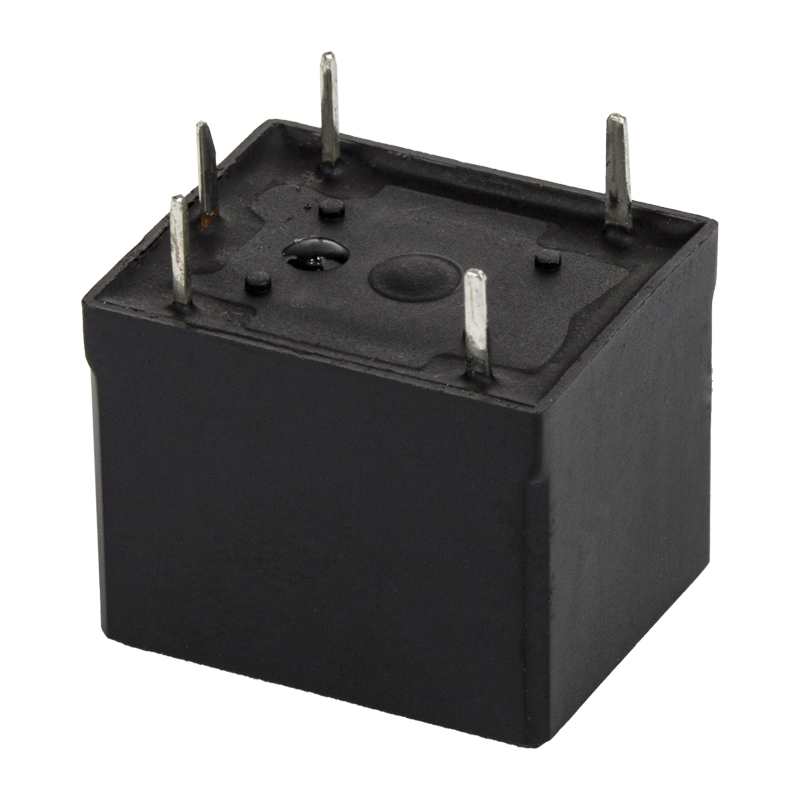 HLS8 T73-Type 5-Pin SPDT Mini Power RelayPCB-mount SPDT relay with Ag alloy contacts, 10A 250VAC rating and coil options from 3 to 48VDC for timer and power-control designs.View Product →
For a typical SPDT output rated 10A at 250V AC, that relay is a 5-pin PCB type with a coil matched to the internal supply, exactly the class of part we build in the T73 and 14F families. If you assemble timers rather than buy them, the questions you put to a relay supplier should mirror the questions a panel builder puts to a timer supplier: contact material, expected operations at rated load, coil power, and whether the footprint matches the board you already have qualified. If you buy finished timers, ask which relay is inside, because that is the component that will need replacing in the field.
The timing circuit decides when the output changes; the output relay decides whether that change survives the load, so both belong on the specification sheet.
Six Datasheet Numbers That Decide Whether an On-Delay Relay Fits
Most selection errors are not about the timing function. They are about a number on page two of the datasheet that nobody compared with the real process. The table below lists the items worth a formal check on every project, together with what to measure before you commit.
| Datasheet item | Typical value | Why it matters | What to confirm |
|---|---|---|---|
| Timing range | 0.1 seconds to 10 hours, split across ranges | Resolution is worst at the bottom of a range | Keep the working setpoint between 30 and 70 percent of the range |
| Repeat accuracy | 0.5 percent digital, 1 to 5 percent analog | Cycle-to-cycle drift shows up as process variation | Log ten cycles with a stopwatch or scope |
| Setting accuracy | Within 5 percent of full scale on analog dials | The dial reads differently from the real delay | Measure the first ten cycles, not the dial |
| Reset time | 30 to 100 milliseconds | A reset longer than the off period stops retriggering | Find the shortest off period in the process cycle |
| Supply tolerance | 85 to 110 percent of rated voltage | Weak transformers extend or block timing | Measure coil voltage while the largest contactor pulls in |
| Output rating | 5A to 30A resistive at 250V AC | The rating is resistive; real loads draw more | Identify the load type and its inrush |
| Ambient temperature | Minus 10 to plus 55 degrees Celsius | Analog timing drifts; contacts derate | Log the temperature inside the closed panel in summer |
Reset time deserves more attention than it usually gets. If a machine cycles every two seconds and the timer needs 80 milliseconds to reset, the device will behave correctly. If the cycle shortens to 60 milliseconds during a fast mode, the timer may never restart cleanly and the output will look erratic. The same logic applies to short interruptions on the supply: a brownout lasting 40 milliseconds may reset the timer and lose the sequence without any visible fault.
Temperature is the other silent variable. A panel that reads 30 degrees Celsius with the door open can sit at 55 degrees Celsius with the door closed and the drives running. Analog RC timers shift their delay in that condition, sometimes by several percent, and relay contact ratings derate as well. If the timing is part of a quality record or a safety sequence, choose a digital unit or verify the analog unit at the real working temperature rather than at room temperature on a bench.
Specify the working setpoint inside 30 to 70 percent of the range, and check the reset time against the shortest off period in the machine cycle rather than the average one.
Coil Voltage, Contact Rating and the Load You Forgot to Count
Two electrical numbers cause more field problems than the timing accuracy ever will: what reaches the coil, and what the contact has to break. Coil voltage looks trivial until you measure it. A 24V DC supply that reads 24.1V on the bench can sit at 20.8V at the end of a long panel run with three contactors energized, which is inside the tolerance of a good wide-range timer and outside the tolerance of a cheap one. On AC coils, the pick-up current is higher than the holding current, so a shared control transformer has to be sized for the worst case, not the sum of the holding figures.
Contact rating is where catalogue numbers mislead. The 10A printed on a relay is a resistive load at 250V AC, measured under defined conditions. A solenoid, a lamp, a capacitor bank or a small motor all draw far more than their steady current in the first few milliseconds, and the contact has to make and break that current. The result is welded contacts, pitted faces, or a relay that clicks but no longer conducts.
Load inrush varies enormously by load type, and the chart below shows the approximate multiples that panel designers commonly work with. Treat it as a starting point for derating, not a substitute for the relay datasheet.
On a 10A output, a 3A solenoid with a five times inrush already asks the contact to make 15A, which is why relay life in that duty can fall well short of the mechanical figure on the datasheet. Moving up to a 30A output relay, such as the T90 and T91 series we build in PCB and quick-connect versions, buys headroom for exactly this kind of load and reduces contact heating. Where the load is a small motor or a lamp bank, an RC snubber or a varistor across the load terminals will cut the arc energy, though it also adds a small leakage path that can keep a neon indicator faintly lit. Silver alloy contacts with cadmium-free formulations are now the norm for RoHS markets, and their behaviour into high-inrush loads is one of the details worth requesting in writing from your supplier.
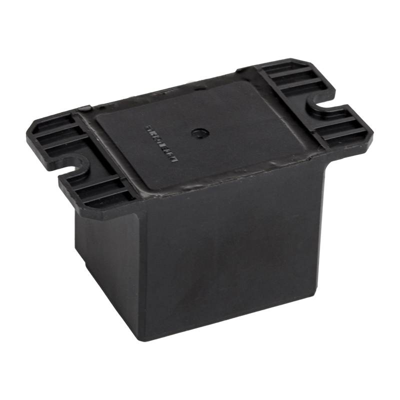 HLS-T91 16F 30A PCB High-Power RelaySPDT 5-pin PCB relay rated 30A at 240VAC, offering contact headroom for high-inrush loads in industrial control and power-switching applications.View Product →
Do not forget the socket. A plug-in relay rated 10A can sit in a socket with lower current capability, and the weakest link in the chain decides the outcome. Check the socket rating, the terminal screw size and the wire gauge before assuming the assembly is good for the relay number.
Select the output relay for the inrush and the socket for the relay, then verify the coil voltage under full panel load; those three checks prevent most on-delay failures.
Wiring an On Delay Relay: Sockets, DIN Rail and Common Mistakes
The wiring around an on-delay timer is short, so mistakes are easy to repeat across an entire panel build. Three habits prevent most of them: identify pins from the printed diagram rather than from memory, keep the coil circuit and the load circuit tidy and separate, and test the finished assembly rather than trusting the bench.
Start with the socket
Plug-in timers land in 8-pin or 11-pin sockets, and coil pins are not in the same place across families. On many 8-pin sockets the coil lands on two opposite pins with the changeover poles spread across the rest, but numbering conventions differ between products and regions, so the diagram moulded into the socket body is the authority. Coloured wiring helps: red and black for coil, black and white for contacts, and a separate colour for the neutral if one is switched.
- Mount the socket on DIN rail with the retaining clip fitted, then wire it before inserting the timer.
- Use ferrules on stranded wire and torque the terminals to the socket maker's figure; loose screws heat up and change resistance.
- Keep the load cable away from analog timing circuits, especially where the timer shares a duct with drive output cables.
- Leave the front dial accessible; an on-delay timer that needs a screwdriver and a mirror to adjust will never be tuned properly.
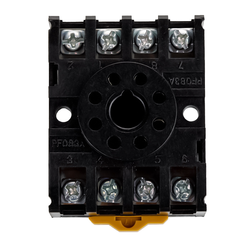 HLS-PF083A Relay Socket for MK2PSocket designed for MK2P relays, suited to plug-in relay installations where matching the relay to a properly rated socket is essential.View Product →
Our own socket range follows the same logic, with 8-pin, 11-pin and 14-pin bodies matched to the 13F, 4453 and MK series relays, so the relay and the socket are rated and tested as a pair rather than assembled from mixed sources.
Suppression changes your timing
A flyback diode across a DC coil is standard practice, and it also slows the drop-out. The coil current circulates through the diode instead of collapsing quickly, which can add tens of milliseconds to the release and quietly change how the circuit behaves when the coil is switched off. On a pure on-delay function this usually only delays the reset. On a related circuit where the output feeds an interlock, that delay can matter, so measure it if the sequence is tight. For AC coils, an RC network or varistor across the coil reduces the switching spike into the timer's supply without holding the armature in.
Testing before handover
- Power the coil from the real control transformer, not from a bench supply with a short lead.
- Time ten cycles with a stopwatch or, better, an oscilloscope on a spare contact, and note the spread.
- Interrupt coil power halfway through the delay and confirm the output never transfers.
- Repeat at the highest expected panel temperature, then record the final dial position and lock it.
Wire from the socket diagram, not from memory, and remember that coil suppression components change the release time of the circuit around the timer.
Where On-Delay Timing Earns Its Place
The on-delay function appears in a small number of recurring patterns across industries. Recognising the pattern tells you which of the datasheet numbers will actually bite.
Motor staging and compressor protection
Compressors and pumps are frequently staged so that a second unit only starts after the first has been running long enough to prove pressure or flow. An on-delay timer between the run signal and the second starter provides that proof window. The same timer family is used to prevent rapid restart after a trip, where a short on-delay built into the reset path keeps the motor from being re-energized before the head pressure falls.
Star-delta transition and reduced-current starting
Star-delta starters use a deliberate delay between star and delta contactors so the motor has time to lose speed before the delta connection is made. Transition timing is typically 30 to 100 milliseconds on small motors and longer on large ones, which is exactly where the reset time and repeat accuracy of the timer become visible in the current waveform. A sloppy timer produces a current spike and contactor wear rather than a clean transfer.
Conveyor and material handling sequences
Starting a belt before material arrives, or giving a jam-clearing bypass a few extra seconds, both rely on on-delay timing. In these applications the timer is often part of a small interlock chain, so a wide-range digital unit with a clear display is easier to adjust during commissioning than a dial hidden behind a cover.
Telecom, automotive and instrument sequencing
In telecom equipment, signal paths are switched in order to avoid hot-plugging into live rails, and the low-current relays on those boards, such as our 2A and 3A SPDT telecom relays in 5-pin and 6-pin PCB formats, are selected for stable contact resistance and long low-level life. Automotive accessory delays, glow plug timing and lamp sequencing use 12V or 24V coils with 25A to 40A contacts, where the relay body rather than the timing logic dominates the design. Instrument panels and appliance control boards use the same on-delay idea at much lower currents, and there the smallest PCB relays in a range carry the function without a socket at all.
Match the timer's output relay to the load family first, then choose the timing technology; the application tells you which number matters most.
Buying On-Delay Timers and the Relays Inside Them
There are two buying situations, and they need different conversations. The first is a panel builder or distributor purchasing finished on-delay timers, where the questions are about function, range, mounting and approvals. The second is a timer manufacturer or an OEM purchasing the relays and sockets that go inside, where the questions are about footprint, coil data, contact material, batch consistency and long-term supply. Both routes benefit from a supplier who can speak about the switching component as fluently as the timing electronics.
- Ask for the certification documents for the exact model, not the family: UL, TUV, CE, CQC and the RoHS declaration should name the part number you are buying.
- Request a sample lot from current production, not engineering stock, and time ten cycles at your real ambient temperature.
- Confirm the footprint and pin layout against the part already designed in, especially where the project is a replacement for an existing board or panel.
- Ask what the manufacturer's own reliability data covers, and whether contact life was measured at resistive load or at a defined inductive load.
- For multi-year programmes, ask about tooling ownership and the change notification process, because a silent contact material change can alter switching behaviour.
Ningbo Helishun Electron has been making relays since 2000, holds ISO 9001:2015 certification, added a second production building in 2003 and has exhibited at the Munich electronics show since 2004. Product design deliberately mirrors the mounting layouts and pin configurations of established international parts, which is what makes pin-for-pin replacement practical for buyers who already have tooling, sockets and drawings in place. That replacement route is only useful if the electrical data is transferred honestly, so we publish coil voltage, contact form, current rating and pin count for every model and expect buyers to verify them against the application.
For buyers sourcing across borders, the practical questions are lead time, packing standard and whether the supplier can support OEM or ODM work rather than only catalogue numbers. A relay manufacturer who already supplies more than 100 countries has usually solved the export documentation and packaging problems that slow a first shipment down, which matters more than a small price difference on the first order.
Buy the part number, not the family: approvals, footprint and contact data must be confirmed for the exact model you are putting into production.
Frequently Asked Questions About Time Delay Relay On Delay Settings
The questions below come up repeatedly in technical enquiries, and most of them can be answered before a sample is even shipped.
What is the difference between on delay and delay on make?
Nothing. On delay, delay on make, delay on energization and the code DOE describe the same behaviour: the output changes only after the set time has elapsed following coil energization. Different manufacturers use different labels, so always read the timing diagram rather than the name on the box.
Can an on-delay timer be turned into an off-delay by swapping the contacts?
No. Reversing normally open and normally closed gives you the opposite state at the same moments, but it does not change the timing. An off-delay device must keep timing or keep its output energized after coil power is removed, which needs stored energy or a separate supply. Order the correct function instead of rewiring around it.
What happens if coil power is removed before the set time expires?
On most on-delay timers the internal timing resets and the output never transfers. When power returns, timing starts from zero. A few models offer accumulated timing or memory functions, but they are the exception rather than the default, so confirm before relying on it.
How accurate is a typical on-delay time delay relay?
Digital units usually repeat within 0.5 percent or better of the set value. Analog RC units typically repeat within 1 to 5 percent and drift more with temperature. Setting accuracy on a dial unit can be worse than repeat accuracy, because the dial marking is only approximate, so measure the real delay rather than reading the knob.
Why does the output chatter when the panel is first switched on?
Usually because the timer's supply is being shared with a large contactor coil or a drive, so the input voltage dips and recovers during power-up. A separate control supply, a small filter, or a timer with a wider supply tolerance and a defined power-up reset will remove it. Analogue timers with a poorly filtered supply are the most prone to this behaviour.
Which relay is normally used as the output inside a timer?
Most panel timers use a miniature power relay, typically SPDT rated 5A to 16A, or an octal plug-in relay on larger housings. PCB timers use a 5-pin or 6-pin power relay soldered directly to the board. The contact material, the coil power and the expected number of operations are the deciding factors.
Do I need a socket, and does it change the rating?
Plug-in timers need a socket, and the socket becomes part of the current path. Its terminal size and current rating can be lower than the relay's, so check both. Sockets also add a small contact resistance, which matters at higher currents and in warm enclosures.
How do I verify an on-delay setting in the field without a timer tester?
Use a stopwatch on ten consecutive cycles and record the spread, or put an oscilloscope on a spare contact if the delay is short. Compare the spread with the repeat accuracy stated in the datasheet. If the spread is much wider, look at supply stability and ambient temperature before blaming the timer.
Measure ten cycles at the real supply voltage and temperature; that single habit resolves most disputes about whether an on-delay timer is faulty or simply specified for the wrong conditions.
On-delay timing is one of the simplest functions in a control panel, which is exactly why it gets specified by habit and then blamed when a sequence misbehaves. The relay waits, transfers, holds and resets. Everything that goes wrong happens at the edges of that description: a load with more inrush than the contact allows, a setpoint squeezed into the bottom of a range, a reset time longer than the off period, or a coil voltage that sags when the panel is busy.
Work through the function, the datasheet numbers, the coil and contact ratings, and the wiring around the socket. When those four items are confirmed, an on-delay time delay relay becomes a dependable part of the sequence rather than a component that gets swapped out every shutdown.


