



 English
 中文简体
Content
- 1 The Direct Answer: Joseph Henry Built the First Electromechanical Relay in 1835
- 2 Electromagnet Versus Relay: Why the Contact Arm Is the Whole Point
- 3 Where the Word "Relay" Came From, and Why Telegraph Companies Embraced It
- 4 Relays as Logic: The 1937 to 1944 Detour That Made Computing Possible
- 5 One Invention, Four Product Families: Where Relay Ratings Actually Land
- 6 What Changed Between Henry's Bench and a Production Line, and What Did Not
- 7 Where Relay Selection Goes Wrong: Six Failures Buyers Actually See
- 8 What to Ask a Relay Manufacturer or Wholesaler Before You Commit
- 9 Frequently Asked Questions
- 9.1 Who invented the electromechanical relay?
- 9.2 When was the electromagnetic relay invented?
- 9.3 Did Samuel Morse invent the relay?
- 9.4 Who coined the word relay?
- 9.5 Why did early computers use relays instead of vacuum tubes?
- 9.6 What is the difference between an electromagnetic relay and a solid-state relay?
- 9.7 Who invented the circuit breaker?
- 9.8 How do I choose between a 5-pin and an 8-pin relay for a control panel?
In 1835, a professor at the College of New Jersey stretched a mile of copper wire through his lecture hall and tried to ring a bell at the far end of it. The battery feeding the line was too weak to drive the bell on its own. So Joseph Henry inserted something in the middle: a small electromagnet whose coil took the line current, pulled a lightweight metal arm down onto a contact, and closed a second circuit powered by a fresh local battery. The bell rang.
That device in the middle is the electromechanical relay. It is the reason a telegraph line could eventually run from the Atlantic coast to California, the reason telephone exchanges clicked for a hundred years, and the reason the first programmable computers used swinging metal arms instead of screens.
The direct answer, before anything else: Joseph Henry invented the electromechanical relay in 1835. He never patented it, never named it after himself, and built it as a by-product of a much more basic problem, which was how to make an electromagnet strong enough to do useful work at a distance.
Why should anyone specifying relays today care about a professor's lecture hall experiment? Because the architecture Henry settled on, a coil plus a magnetic circuit plus a moving armature plus one or more contact pairs, is still exactly what you are buying when you order a relay. Every line on a modern datasheet, from must-operate voltage to contact material to mechanical life, is a refinement of the question he first framed: how little energy can I use to control how much energy?
The Direct Answer: Joseph Henry Built the First Electromechanical Relay in 1835
Joseph Henry was born in Albany, New York, in 1797. He was apprenticed to a watchmaker, taught school, and ended up as a professor at Albany Academy before moving to the College of New Jersey in 1832. He later became the first Secretary of the Smithsonian Institution, which is why his laboratory notes and instruments are still archived in Washington.
His route to the relay started with a mechanical weakness. The electromagnets of the 1820s were feeble. William Sturgeon's 1825 horseshoe electromagnet, generally accepted as the first practical one, used a single layer of bare copper wire wound around a soft iron core and could lift roughly nine pounds. You could not wind more layers, because bare wire shorted against itself.
Henry's contribution was unglamorous and decisive: insulation. By covering the wire, famously with silk, he could wrap layer after layer around the same core, multiplying the magnetic effect of the same current. By 1831 he had built a magnet at Yale that lifted more than a ton. That work is what made a relay possible in the first place, because a relay needs a coil that responds to a small, distant current rather than a large, local one.
His 1835 experiment put the two halves together. A long, thin wire coil, tuned for a small current over a long line, drove an armature. The armature closed a contact in a second, local circuit with a strong battery. The relay did not create energy. It spent a small amount of energy to control a large amount, which is the same trick a valve plays in a water pipe.
Henry published the idea openly and declined to patent it, believing that scientific results should circulate. That decision matters for the attribution story, because it handed the commercial development of the relay to other people.
| Year | Name | What was added |
|---|---|---|
| 1825 | William Sturgeon | First practical electromagnet: horseshoe iron core, single layer of copper wire, lifts about nine pounds. |
| 1831 | Joseph Henry | Multi-layer insulated windings; a magnet at Yale lifts over a ton; small magnet used to switch a larger circuit. |
| 1835 | Joseph Henry | First electromagnetic relay: line current in a many-turn coil closes a contact in a separate, stronger local circuit. |
| 1836 | Edward Davy | British telegraph patent describing a repeating relay; the word "relay" enters technical vocabulary. |
| 1837 | Samuel Morse and Alfred Vail | American telegraph patent application; the relay becomes a practical line repeater. |
| 1924 | Hugo Stotz | Resettable miniature circuit breaker, protection built on the same contact-opening logic. |
| 1937 | George Stibitz | Relay-based binary adder assembled on a kitchen table; relay computing begins. |
| 1941 | Konrad Zuse | The Z3, a fully relay-based programmable computer, runs in Berlin. |
| 1947 | Bell Telephone Laboratories | The transistor, after which relays begin a slow retreat from logic circuits. |
Electromagnet Versus Relay: Why the Contact Arm Is the Whole Point
An electromagnet produces motion. A relay produces a switched circuit. The difference is the contact assembly, and that is why historians credit Henry with the relay and Sturgeon only with the magnet.
Henry also worked out a distinction that engineers still use every day, though the vocabulary has changed. He separated what he called intensity magnets from quantity magnets. An intensity magnet used many turns of fine wire, had high resistance, and responded to the low currents and high voltages you get at the far end of a long telegraph line. A quantity magnet used few turns of thick wire, had low resistance, and delivered brute force from a local battery with large plates. A relay is essentially an intensity magnet driving a quantity circuit.
That pairing is the ancestor of the coil-and-contact split you see on any modern datasheet. The coil side is specified in volts and ohms and must-operate current. The contact side is specified in amps, volts, load type, and expected operations. The two sides are electrically isolated from each other, often to several thousand volts, and that isolation is the reason relays remain in designs that already contain transistors.
Look at the modern catalogue and the same logic is visible in the numbers. A telecom relay such as a 5-pin 3A PCB type carries a coil that draws a small, steady current and a contact set rated for signal-level switching in communication equipment. A general power relay rated 30A handles the opposite end of the same spectrum. Both are Henry's device with better materials.
Where the Word "Relay" Came From, and Why Telegraph Companies Embraced It
The name has nothing to do with electronics. A relay was a fresh horse. On a fast coach route, horses were stationed at intervals so a tired team could be swapped for a rested one, and the posting station was called a relay. When telegraph engineers needed a device that took a weakened signal and handed it on refreshed, the riding metaphor fit perfectly.
Edward Davy, a British physician and inventor, used the term in his telegraph patent work of the mid-1830s, and the word travelled from there. Samuel Morse and Alfred Vail built the relay into the American telegraph system that grew through the 1840s, and by the 1860s repeater stations stood every forty to sixty miles along the line, each one with a local battery and a relay that re-sent whatever arrived.
The engineering reason was simple arithmetic. A telegraph line has resistance that grows with length, and leakage to earth that grows with length as well. Beyond a certain distance the receiving magnet no longer has the strength to pull its armature. A relay placed before that point reads the weak signal and regenerates it, and the process repeats. Long-distance telegraphy, and later long-distance telephony, was a chain of relays all the way down the wire.
This is also the era when the relay became a manufactured product rather than a laboratory curiosity. Workshops began producing standard coils, standard armatures, and standard contact springs, and the idea of a catalogue part with interchangeable dimensions was born. Anyone sourcing relays from a manufacturer today is still buying into that nineteenth-century idea of the interchangeable part.
Relays as Logic: The 1937 to 1944 Detour That Made Computing Possible
For a century the relay was a communications component. Then, in 1937, George Stibitz at Bell Telephone Laboratories took two relays home to his kitchen table in New Jersey, wired them to flashlight bulbs and a battery, and built a machine that added binary numbers. His employer called it the Model K. Colleagues called it the kitchen computer.
What followed scaled quickly. The Complex Number Calculator of 1940 handled arithmetic on complex numbers over telephone lines, and a demonstration at Dartmouth College that year is often described as the first remote use of a computer. In Berlin, Konrad Zuse finished the Z3 in 1941 with roughly two thousand relays and a clock of a few hertz. In Cambridge, Massachusetts, the Harvard Mark I of 1944 combined thousands of relays with mechanical counters and stretched fifty-one feet long. Telephone exchanges, meanwhile, had been switching calls with relay-driven crossbar systems since the late 1930s.
Relays were chosen for these machines for a reason that resonates with buyers today: they were the only switch that was reliable, cheap, well understood, and available by the thousand. They did not need the fragile vacuum tubes of the period, they worked on ordinary DC supplies, and their on/off behaviour was unambiguous.
They also had limits that ended the era. A relay takes roughly one to ten milliseconds to operate, which caps a machine at a few hundred operations per second. Contacts bounce on closure, produce electrical noise, and wear out after somewhere between a million and a hundred million operations depending on load. Relay logic consumed real power, generated audible clatter, and occupied entire rooms. The transistor of 1947 removed all four constraints, and by the 1960s solid-state devices had taken over logic while relays retreated to the jobs they still do best: switching real loads, providing isolation, and holding a state without power.
One Invention, Four Product Families: Where Relay Ratings Actually Land
The distance between Henry's lecture hall and a modern catalogue is best seen in the numbers, not the dates. A full relay range spreads from milliamps of coil current up to eighty amps of contact current, and the spread is not evenly distributed across families.
A representative catalogue of forty-five relay product pages shows where the engineering effort sits: the broad middle of general-purpose switching, a large supporting cast of sockets, a compact automotive group, and a small, specialised telecom group. The chart below reflects that composition.
The shape of that chart tells a buyer something practical. Most of the choice sits in general power relays because that is where control panels, appliances, and industrial equipment place the widest variety of demands, with contact forms running from single-pole single-throw through double-pole double-throw and pin counts from five to fourteen. The socket group is nearly as large, which reflects a simple field reality: a plug-in relay is only as good as the socket under it, and buyers who standardise on a socket family gain a maintenance advantage that outlasts any single relay model.
Automotive relays form their own cluster because the requirements diverge sharply from panel relays. Loads are inductive and dirty, currents reach 25A, 40A, and 80A, and the package has to survive vibration, salt spray, and wide temperature swings. Telecom relays sit at the opposite extreme, with ratings of 2A and 3A and an emphasis on low-level signal integrity rather than brute force.
What follows from this is a sourcing rule rather than a technical one. If a supplier's range is concentrated in only one of those four groups, the other three are likely bought in rather than made, and the datasheets may not be backed by the same test data. A factory that covers all four, with its own tooling and its own life-test benches, is easier to audit and easier to hold to a specification over several years of shipments.
 HLS6-4100H-1 5-Pin SPDT Telecom Relay, 3A PCB-MountA 3A PCB-mount SPDT telecom relay with Au+Ag contacts and 3–24 VDC coil options, worth checking for communication-equipment switching where contact resistance stability matters.View Product →
The telecom end of the range is where Henry's intensity magnet logic survives most visibly. A 5-pin SPDT telecom relay with a 3A rating and PCB pins is designed to take a modest coil drive and pass a clean signal through communication equipment, where the enemy is contact resistance drift rather than arcing. Selection here should focus on contact material, low-level switching capability, and stability of the operate voltage across temperature.
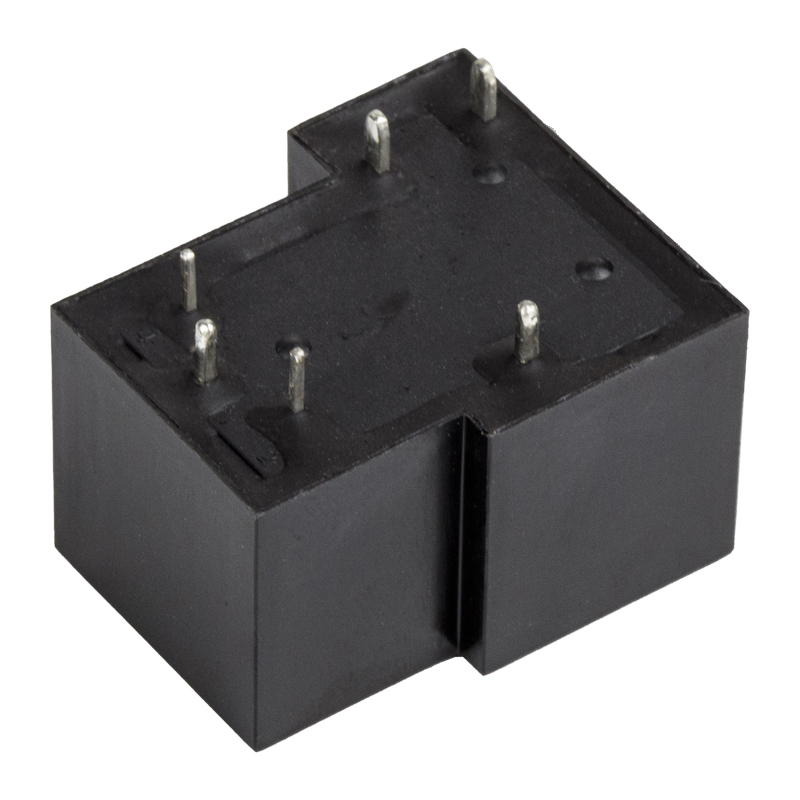 HLS-T90(15F) 30A SPDT General Power RelayThe workhorse 30A PCB power relay for appliance control boards, power supplies and control cabinets, available in 5- or 6-pin versions with multiple coil options.View Product →
The centre of the chart is the workhorse. A 5-pin or 6-pin SPDT power relay rated 30A with PCB pins covers the everyday job in appliance control boards, power supplies, and control cabinets, and it is the model most often compared across suppliers. When buyers ask for a quotation on a 30A power relay, the questions that actually decide the outcome are derating at ambient temperature, contact material and its RoHS status, and the mechanical life figure measured at rated load rather than at no load.
 HLS-CMA3-1 Custom 80A PCB Automotive RelayA custom 80A automotive relay with PCB quick terminals and 6–24 VDC coil options, positioned for high-power loads that require close thermal and vibration review.View Product →
The automotive corner of the range is the least forgiving. A 5-pin 80A relay with PCB or quick-connect terminals sits on loads such as starter circuits, cooling fans, and high-power lighting, where inrush current can be several times the steady-state rating and where the relay must keep working after thousands of thermal cycles. Automotive buyers usually want shock and vibration data, dimensional tolerance drawings, and material declarations alongside the electrical specification.
What Changed Between Henry's Bench and a Production Line, and What Did Not
Almost every material in the device has been replaced. Almost none of the physics has. The comparison below is the one worth keeping in mind when a supplier claims a relay is "completely new".
| Aspect | Henry's relay, 1835 | A modern production relay |
|---|---|---|
| Coil winding | Hand-wound, silk-insulated copper, many layers | Machine-wound, class B or F insulation, hundreds to thousands of turns |
| Magnetic circuit | Soft iron core and bar armature | Laminated or solid iron with defined air gap and pole faces |
| Contact material | Bare copper or brass | Silver alloys, silver-tin oxide for power, gold-clad for low-level signals |
| Coil drive | Primary cell, a few volts, unstable | 3 to 48 VDC nominal, must-operate typically at or below 75 percent of nominal |
| Operating time | Visibly slow, hand-tuned | Roughly 5 to 15 milliseconds pull-in, a few milliseconds release |
| Life expectancy | Unmeasured, likely hundreds of operations | Hundreds of thousands to tens of millions of electrical operations, more mechanically |
| Isolation and spacing | Not standardised | Creepage and clearance tables in IEC 61810 and UL 508 |
| Approvals | None | UL, TUV, CQC, CE marks, RoHS and REACH declarations |
Four things did not change at all. The coil is still copper, and its resistance still rises with temperature, which is why a relay that picks up cleanly at 20 degrees C may chatter in a cold start at minus 20. The magnetic circuit still loses force as the air gap opens, which is why contact pressure falls as contacts wear. The contact is still a compromise between low resistance and resistance to arcing, and no alloy wins both. And inertia still sets the speed limit, which is why an electromechanical relay will never switch in microseconds.
What did change is repeatability. Henry could not tell you what his relay would do on the ten-thousandth operation. A modern manufacturer publishes a life curve, a derating chart, and a tolerance drawing, and can supply test reports for a specific production lot. That documentation, more than the materials, is what separates a component from an experiment.
Where Relay Selection Goes Wrong: Six Failures Buyers Actually See
Most field failures blamed on relays are not manufacturing defects. They are specification mismatches that were invisible on the purchase order. These six account for a large share of returns across appliance, industrial, and automotive programmes.
- Coil voltage checked only at room temperature. A relay with a 12 VDC coil and a must-operate figure of 75 percent needs about 9 V to pull in. In a cold cabinet the coil resistance drops and the available voltage sags, and the margin disappears. Always ask for the must-operate and must-release values, not just the nominal voltage.
- Contact rating read without the load type. A 10A resistive rating does not cover a 10A motor, a tungsten lamp with a cold-filament inrush many times higher, or a DC load that cannot rely on a zero crossing to extinguish the arc. Derating for DC inductive loads is often the single largest correction a buyer has to make.
- Footprint compatibility assumed rather than measured. "Same layout as imported types" is a useful claim but not a drawing. Pin pitch, pin diameter, overall height, and the position of the mounting tab all matter, and a half millimetre of pin spacing error stops a production line.
- The socket treated as an accessory. In plug-in installations the socket carries the same current as the relay and adds its own contact resistance. Socket terminal material, screw torque, and retention clips decide whether the assembly survives a year of thermal cycling.
- Certificate scope taken for granted. A UL file number covers specific models and specific ratings. Two relays from the same family with different contact materials may not share the same approval, and shipping the wrong variant into a listed assembly creates a compliance problem downstream.
- Mechanical life quoted where electrical life was needed. A figure of ten million mechanical operations tells you the mechanism survives. It says nothing about how long the contacts last at rated current, which is typically far lower and is the number that governs field returns.
None of these require a laboratory to catch. They require a checklist and a supplier willing to answer specific questions in writing, which is a far better filter than a sample that happens to work on the bench.
What to Ask a Relay Manufacturer or Wholesaler Before You Commit
Henry's relay had one advantage over a modern supply chain: he built the only unit in existence and knew its history personally. Buyers do not have that luxury, so the questions have to do the work instead.
Experience is a reasonable first filter. Ningbo Helishun Electron has been manufacturing relays since 2000 from an 8,800 square metre plant, with UL and CQC certification of its products achieved in 2001, the HELISHUN trademark registered in 2002, ISO 9001 quality system certification in 2003, and first participation in the Munich electronics exhibition in 2004 as overseas sales opened up. Offices in Guangzhou and Shenzhen support domestic customers, and the company describes sales into more than a hundred countries alongside OEM and ODM cooperation, which matters if the requirement is a modified coil, a different contact material, or a custom harness rather than a catalogue part.
That history is useful context, but it does not replace a document request. A serious supplier will answer the following without hesitation.
- Which approval file number covers this exact model and rating, and can the certificate be supplied with the quotation?
- What are the must-operate and must-release voltages, and how do they shift between minus 40 and plus 85 degrees C?
- What is the contact material, and is there a current RoHS and REACH declaration for that material?
- Is life-test data available at rated load rather than at no load, and over how many samples?
- Which socket is the matched part for this relay, and what torque should the terminals be tightened to?
- For automotive programmes, can dimensional reports, vibration and shock data, and material declarations be provided?
- For distribution and wholesale volumes, what are the minimum order quantity, the production lead time, and the sample lead time?
The pattern behind those questions is the same one Henry discovered on his bench. A relay is a device whose behaviour depends on conditions, and a specification that does not state its conditions is not a specification. Suppliers who can answer conditionally, with numbers and documents, are the ones whose parts behave predictably in a cabinet in summer and a cold store in winter.
Frequently Asked Questions
Who invented the electromechanical relay?
Joseph Henry, an American physicist working at the College of New Jersey, now Princeton University, built the first electromagnetic relay in 1835. He used a many-turn insulated coil to detect a weak current arriving on a long wire, and the resulting movement closed a separate, stronger local circuit. He published the result and declined to patent it, which is why his name is less familiar than the telegraph operators who commercialised the idea.
When was the electromagnetic relay invented?
The commonly cited year is 1835, though the groundwork ran from 1825, when William Sturgeon built the first practical electromagnet, to 1831, when Henry demonstrated magnets of far greater strength using multi-layer insulated windings. The relay was the application of that improved magnet to the problem of long-distance signalling.
Did Samuel Morse invent the relay?
No. Morse and Alfred Vail built the relay into a practical telegraph system and their 1837 patent application is a landmark in telegraphy, but the device itself came first. Morse's contribution was system design, coding, and commercial deployment rather than the switching element, and even his system depended on Henry's published work on electromagnets.
Who coined the word relay?
The term comes from horse transport, where a relay was a station holding fresh horses for a coach. It moved into telegraphy in the 1830s, appearing in British patent work by Edward Davy, because the device performed the same refresh function as a change of horses: it took a tired signal and passed it on renewed.
Why did early computers use relays instead of vacuum tubes?
Reliability and availability. Relays in the late 1930s were cheap, mass produced by the telephone industry, and understood. Vacuum tubes were fragile, hot, and short-lived. Relay machines such as the Z3 and the Harvard Mark I therefore used thousands of them, until the transistor of 1947 removed the speed and wear penalties that had capped relay computing.
What is the difference between an electromagnetic relay and a solid-state relay?
An electromagnetic or electromechanical relay moves physical contacts, giving very low on-resistance, complete galvanic isolation, and no leakage in the off state, but it wears and switches slowly. A solid-state relay switches semiconductors, giving fast, silent, unlimited operation, but it has leakage current, voltage drop, and limited surge tolerance. Most equipment needs both, used where each is stronger.
Who invented the circuit breaker?
A resettable miniature circuit breaker is generally credited to Hugo Stotz, who patented the concept in the 1920s. It builds on the same contact-opening mechanism as a relay and belongs to the same family of electromechanical switching devices. Earlier protection relied on fuses, which had to be replaced rather than reset.
How do I choose between a 5-pin and an 8-pin relay for a control panel?
Start from the contact form, not the pin count. A 5-pin part is usually a single-pole device with one changeover contact, while 8-pin parts commonly provide two changeover contacts in a double-pole arrangement. Then check coil voltage, contact rating at the real load, pin pitch, and the matched socket. If the panel needs a second independent circuit switched at the same time, the 8-pin form usually wins on wiring simplicity.
The story of the electromechanical relay runs from a mile of silk-covered wire in a New Jersey lecture hall to an eighty-amp part bolted into a vehicle, and the thread running through it never broke. A small, isolated signal controls a larger one, and the price of that control is a set of compromises in coil resistance, contact material, magnetic force, and moving mass.
That is also why buying a relay is mostly an exercise in reading conditions rather than reading claims. The invention is nearly two centuries old and entirely settled. What varies, part by part and supplier by supplier, is how honestly the conditions are documented, and how much of the original Henry logic survives in the coil, the armature, and the contact set you actually receive.


