



 English
 中文简体
Content
- 1 What a Temperature Control Relay Does Inside a Control Loop
- 2 The Four Numbers That Decide Whether the Relay Survives
- 3 Matching Contact Rating to the Thermal Job
- 4 AC Heater Switching and DC Heater Switching Are Different Problems
- 5 Hysteresis, Short Cycling and the Contact Wear Nobody Budgets For
- 6 The Coil Side: Driving a Temperature Control Relay from a Controller
- 7 Sockets, Panel Layout and Serviceability
- 8 Verification: What to Test Before You Approve a Batch
- 9 Qualifying a Temperature Control Relay Manufacturer, Supplier or Wholesaler
- 10 Cost, Lead Time and the Inventory Traps
- 11 Frequently Asked Questions
- 11.1 Can a temperature control relay switch a 2 kW heater at 230 V AC?
- 11.2 Should I use a relay or a solid-state relay for temperature control?
- 11.3 How do I keep relay contacts from welding shut?
- 11.4 What coil voltage should I choose, 12 V or 24 V?
- 11.5 How many operations can a temperature control relay last?
- 11.6 Do I need a socket, or can I solder the relay directly?
- 11.7 Which certifications matter for export?
- 11.8 Can a manufacturer supply OEM or ODM versions?
An appliance manufacturer once returned a batch of countertop ovens because the heating element would not switch off. The thermostat was reading the chamber correctly. The temperature control relay soldered to the control board had welded its contacts closed after roughly 60,000 operations against a datasheet figure of 100,000. The part was rated 16 A, the heater drew 15.2 A at nominal mains, and every document in the file looked correct.
That kind of failure is why this topic deserves more than a glance at a datasheet. A temperature control relay takes a low-power decision from a sensor or controller and turns it into the high-current action that heats, cools, or holds a process at setpoint. It sits between two very different electrical worlds, a 3.3 V or 24 V control side and a 230 V or 400 V load side, and it absorbs everything the load throws back at it: inrush current, inductive kickback, cabinet heat, and hundreds of thousands of mechanical operations.
The short answer, before the detail: size the relay for the load, not for the setpoint. Read the real current at the real ambient temperature, apply a margin that matches the load type, and only then choose the coil voltage and pin layout that fit your board or panel. Get that order right and most field failures disappear before the first prototype is built.
What a Temperature Control Relay Does Inside a Control Loop
A temperature control loop has four parts: sensing, decision, switching, and load. The relay owns the third part, and it is the only component that touches both the logic-level world and the mains-level world.
On the control side the relay behaves like an inductor with a rated voltage. On the load side it behaves like a pair of metal contacts with a limited appetite for current. The two sides are separated by an air gap that might be half a millimetre wide and still provide several kilovolts of dielectric strength. That gap is the reason the relay keeps winning design slots in heating appliances: when the contacts open, the load is genuinely dead, with no leakage current keeping an element warm or an indicator glowing faintly in a dark kitchen.
Contact form is the first practical decision. A single-pole single-throw normally open relay covers simple on/off heating. A single-pole double-throw part gives changeover, which helps when one controller drives heating in one state and a cooling fan or damper in the other. A double-pole double-throw relay switches two independent circuits from one coil, which appears often when a device needs a heater contact and a separate alarm or interlock contact that must move at the same instant.
Pin count and body size follow from that choice. A 5-pin SPDT relay is the workhorse of small appliance control boards. Eight-pin bodies appear in panel-mounted controllers. Eleven-pin and fourteen-pin transparent relays belong to the socket-mounted industrial tradition, where one footprint serves three-pole and four-pole switching and the wiring stays in the socket when the relay is replaced.
It is worth being clear about what the relay is not. It is not the sensor, and it does not decide the setpoint. In a low-cost appliance a bimetallic thermostat may do both jobs in one part, but as soon as a microcontroller enters the design the functions separate, and the relay becomes a component with its own specification, its own failure modes, and its own safety role. In a heater circuit a welded contact means a heater that keeps running, which turns a warranty issue into a certification and liability issue.
Five lines on a datasheet carry most of the decision weight: contact form, contact rating, coil voltage, electrical life, and dielectric strength. Everything else, from seal type to terminal plating, is refinement around those five.
The Four Numbers That Decide Whether the Relay Survives
Most selection errors trace back to one of four numbers, and none of them appear on the headline line of a datasheet.
1. Real load current at nominal and at maximum mains
Mains tolerance of plus or minus ten percent, heater resistance tolerance of five to ten percent, and a cold element with lower resistance than a hot one can push a comfortable 14 A design past 17 A. Measure the current in the finished enclosure rather than trusting the nameplate on the heater.
2. Load type and the inrush it delivers
A resistive heater is gentle. A tungsten lamp, a compressor, or a solenoid valve is not, and a DC load behaves differently again because the arc has no zero crossing to extinguish it.
3. Ambient temperature inside the cabinet
Contact ratings are quoted at a reference temperature, often 23 °C or 40 °C. A relay sitting next to a 200 °C oven wall, inside a sealed plastic housing, is operating at 55 °C to 70 °C and its current capability drops accordingly. This is the single most common mismatch in appliance designs.
4. Duty cycle and expected operations
Multiply cycles per hour by operating hours per year by service life in years. A process that cycles every 20 seconds while running 12 hours a day passes 2,160 cycles per day, which is 788,000 cycles per year. No small relay enjoys that number.
| Load type | Typical inrush | Suggested margin over steady current | Practical note |
|---|---|---|---|
| Resistive heater, AC mains | 1.0 to 1.5 times | 1.25 to 1.5 times | Watch cabinet temperature and terminal heating |
| Tungsten or halogen lamp | 8 to 15 times | 3 to 5 times | Cold filament inrush; short cycles erode contacts fastest |
| Compressor or fan motor | 5 to 8 times | 2.5 to 4 times | Locked-rotor current; a contactor above roughly 1 kW |
| Solenoid valve or small pump | 3 to 6 times | 2 to 3 times | Suppress coil kickback at the load, not only at the relay |
| DC heater at 12 V or 24 V | 1.0 to 1.2 times | 1.5 to 2 times using the DC curve | Arcs do not self-extinguish; the AC rating is irrelevant here |
| Transformer or capacitive supply | High peak, short duration | 2 to 3 times | Peak current can far exceed what the meter shows |
Margins compound rather than replace each other. A 15 A load with a 1.5 margin and a 0.8 thermal derating factor points to a nominal rating near 28 A, which is why a 30 A class body often appears in equipment that looks, at first glance, like a 15 A job. That overshoot is not waste; it is the difference between a relay that reaches end of life with the appliance and one that reaches it in the field.
Matching Contact Rating to the Thermal Job
Across one general power relay line, the same 5-pin footprint appears in several current classes, and buyers are often surprised by how little the body changes between them. The chart below compares nominal contact ratings of five families that turn up most often in heater, oven, and compressor control, so the jump points are visible before a part number is fixed.
Nominal contact rating by relay family
Nominal ratings at 250 V AC for the families shown. Each datasheet load curve and life figure should be checked for the actual application.
The pattern matters more than the individual bars. Moving from a 10 A mini body to a 15 A or 20 A part usually costs a few millimetres of height and a slightly heavier terminal, which is easy to absorb on an existing board. The 30 A class is a different animal: wider terminal spacing, more contact force, more coil power, and a footprint that rarely drops into a 10 A pad layout without a board revision. That is precisely why the decision is worth making at the beginning of a project rather than after the tooling is cut.
For oven and water-heating loads in the 2 kW to 6 kW range, a 30 A class relay with a generous margin is a common and sensible answer, particularly when the enclosure runs warm. A 5-pin 30 A high power relay such as the T90 series covers exactly that band, with PCB pin and quick-connect terminals available so the same electrical design can serve a board-mount version and a wired version.
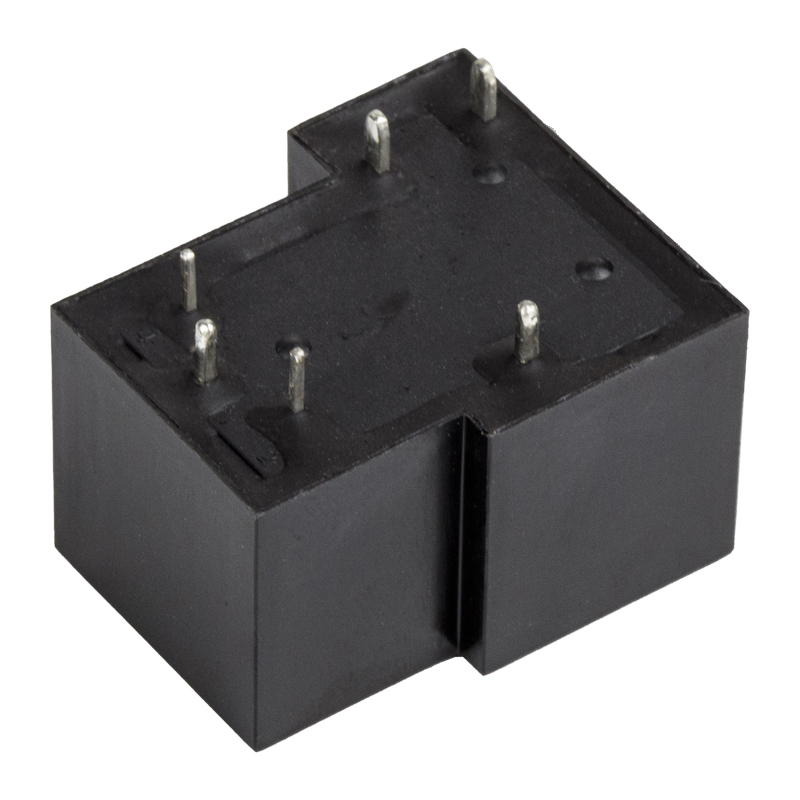 HLS-T90 30 A High-Power PCB RelayA 30 A-class SPDT relay for heating and industrial loads, offered with PCB pins and quick-connect terminals to support board-mount or wired designs.View Product →
Below that band, small appliances and instrument heaters usually sit between 5 A and 15 A, where mini SPDT parts keep the board compact and the coil drive simple. Above it, the sensible move is out of the PCB relay category entirely and into a contactor, because a relay carrying more than roughly 30 A continuously becomes a heat source with terminals attached.
AC Heater Switching and DC Heater Switching Are Different Problems
An AC contact opens twice per cycle at the zero crossing, and the arc extinguishes on its own within a few milliseconds. That natural quenching is a large part of why AC ratings look generous. A DC contact has no zero crossing, so the arc sustains until the gap grows long enough or the current falls; the same contact pair that handles 30 A at 250 V AC may be comfortable at only a few amps at 24 V DC.
This distinction catches designers in three places: low-voltage cartridge heaters in packaging and drying equipment, battery-powered heating in portable devices, and 12 V or 24 V vehicle systems where a heater, glow plug, or fan draws tens of amps. In each case the correct input is the DC load curve, not the AC headline rating.
Practical measures that help on DC loads:
- Use the manufacturer's DC curve and stay well inside it, or move up two voltage classes.
- Prefer relays intended for automotive DC switching, where contact materials and blowout magnets were designed for sustained arcs.
- Split the load across two poles in series when the contact arrangement allows it.
- Suppress inductance at the load, not only at the coil, so kickback does not erode contacts.
- Avoid capacitive filters directly across the contacts; stored energy discharges into the gap during opening.
Automotive relays are a good illustration of the split. A 5-pin 80 A PCB or quick-connect type such as the HLSCMA31 exists because 12 V and 24 V systems ask for high current at low voltage, with inrush from motors and lamps that would destroy a general-purpose AC part. The construction is heavier, the terminals are wider, and the life curves are drawn for DC.
On the AC side, a small snubber across the contacts can reduce arcing on inductive loads, but it also passes a small leakage current when the relay is open. In a heater circuit that leakage is harmless; in a circuit that drives a sensitive input or a neon indicator, it can cause flicker. Choose snubbers for the load, and place coil suppression on the coil, where it belongs.
Hysteresis, Short Cycling and the Contact Wear Nobody Budgets For
Temperature controllers are usually tuned for accuracy, and relay contacts pay for that accuracy. A 0.5 °C deadband combined with 1.5 °C of overshoot on a 1.5 kW air heater can produce a cycle every 10 seconds. Over a 10-hour shift that is 3,600 operations a day, roughly a million a year, on a component whose electrical life at full load may be 100,000 operations.
The fix is rarely a bigger relay. It is control strategy:
- Widen the deadband to what the process can actually tolerate; air ovens and reflow chambers usually accept 2 °C to 5 °C without complaint, liquid baths rather less.
- Add a minimum on-time and a minimum off-time in firmware, so a noisy sensor reading cannot toggle the output.
- Use time-proportioning control with a cycle time of 10 to 30 seconds instead of on/off control at every sample. The heater sees a duty ratio rather than a stream of short pulses.
- Filter the sensor in software before the comparison, especially with thermocouples in electrically noisy cabinets.
- Move to a solid-state output only when the required cycle time drops below a few seconds, and accept the leakage and heatsink consequences that come with it.
Short cycling also damages the load side of the system. A heater that switches on for three seconds never reaches its steady thermal output, and the resulting current waveform is dominated by cold-resistance inrush. The relay absorbs erosion, the element absorbs thermal stress, and the user sees temperature instability that looks like a sensor fault.
One more habit worth adopting: separate the control contact from the safety contact. Run the heater through a contact that the controller modulates, and use a second, independent contact or a thermal fuse for the overtemperature cutout. Sharing one contact for both duties means the safety function inherits every cycle of wear the control function generates.
The Coil Side: Driving a Temperature Control Relay from a Controller
Coil voltage decides how the relay talks to the controller, and the common options are 5 V, 12 V, and 24 V DC, with 110 V and 230 V AC coils still present in retrofit and industrial panel work. A 12 V temperature control relay is the usual choice for appliance boards and small machines; 24 V DC dominates industrial panels because it matches PLC outputs and reduces current on long runs.
Three coil parameters deserve attention:
- Must-operate voltage, typically around 75 percent of nominal. A 12 V relay that will not pull in reliably at 10.8 V is a design risk in systems with long supply cables.
- Must-release voltage, typically five to ten percent of nominal. Too low a release threshold means chatter when the supply sags.
- Coil power, often 0.36 W to 0.9 W. Multiplied across a panel of twenty relays, that becomes a real heat load inside a sealed enclosure.
Driving the coil from a microcontroller is simple but not trivial. A small NPN transistor or a low-side driver with a base resistor handles the current; a flyback diode across the coil absorbs the inductive spike at switch-off. That diode also slows the release by a few milliseconds, which matters in circuits that switch frequently or that need fast drop-out on power loss. A diode plus Zener combination gives faster release at the cost of a higher clamping voltage, which the driver must tolerate.
AC coils need an RC suppression network rather than a diode, and the resulting phase shift can delay release noticeably. Long control cables running beside mains wiring can couple enough noise into a high-impedance coil circuit to cause spurious operation; twisting the coil pair or adding a small capacitor at the driver usually settles it.
Magnetic latching relays solve the holding-power problem, since the coil only draws current during the transition. They are attractive for battery equipment and for panels where dozens of relays stay energised for hours, but they add state uncertainty at power-up, which is a real drawback in a heating appliance that must fail safe.
Sockets, Panel Layout and Serviceability
In panel-mounted controllers the relay rarely sits on a PCB. It plugs into a socket, and the socket is where the wiring lives. That arrangement turns a relay replacement into a two-minute task instead of a rewire, which matters in food service equipment, HVAC panels, and any machine where downtime is measured in lost production rather than in component cost.
Sockets bring their own engineering questions. Each socket adds two contact interfaces between the relay pin and the wire, and each interface adds resistance and a potential hot spot. A socket rated 10 A paired with a 16 A relay is a fire waiting for a busy shift, so match the socket rating to the relay rating, not to the wire gauge alone. Terminal torque, wire gauge, and DIN-rail spacing all affect temperature rise inside the cabinet, and stacked sockets in a warm enclosure derate faster than a single relay on a bench.
The industrial transparent relay families make this pairing explicit. An 8-pin DPDT transparent relay with a 10 A rating is a familiar sight in control cabinets, and its matching socket presents the coil and contact terminals in a fixed, screw-terminal layout that electricians already know.
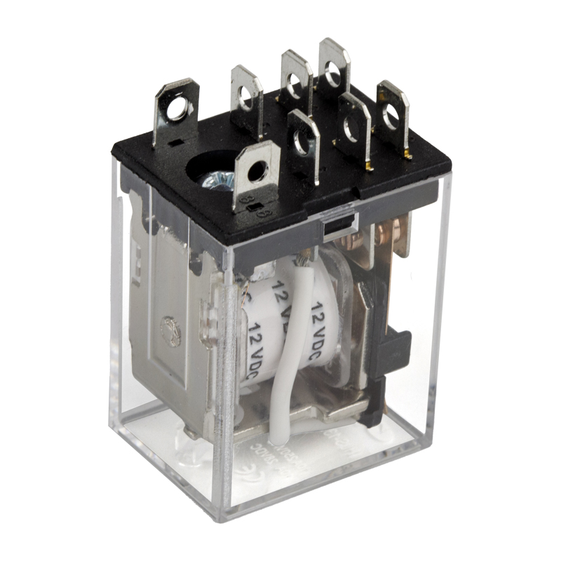 HLS-13F-2 Transparent 8-Pin 10 A Power RelayAn 8-pin 2C transparent relay rated 10 A, with quick-connect PCB pins and Ag alloy contacts for control-cabinet and general industrial switching.View Product →
For socket-mounted builds, the pairing should come from one source. A relay socket designed for the 13F1 or 13F2 body, with the correct pin circle, retention clips, and terminal spacing, keeps the contact path short and the replacement repeatable.
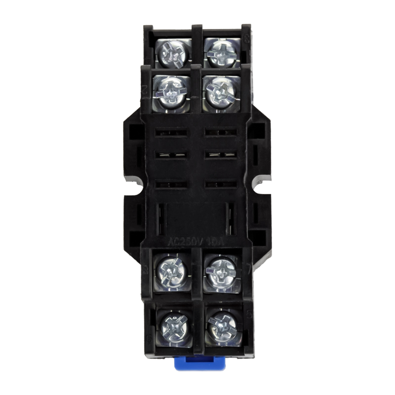 HLS-PTF08A-01 Relay Socket for 13F-1/13F-2A socket for 13F-1 or 13F-2 relays, intended to pair socket-mounted builds from one source and support repeatable relay replacement.View Product →
Mounting height also deserves a thought during panel layout. Relays mounted directly above a transformer or a contactor run hotter than the datasheet assumes, and heat rises. Leaving one DIN-rail slot of clearance under the power components is cheaper than moving to the next current class. Where service access is tight, side-mounted retaining clips beat friction-only retention, because a relay that creeps out of a socket under vibration creates intermittent faults that are painful to diagnose in the field.
Verification: What to Test Before You Approve a Batch
Approving a temperature control relay on datasheet numbers alone is how marginal parts enter a bill of materials. A short, disciplined test sequence catches most of the risk in under two weeks:
- Contact resistance on a sample of at least twenty pieces, before and after a thermal soak at the maximum rated ambient.
- Pull-in and drop-out voltage across the batch, at both cold start and after twenty minutes of coil energisation.
- Dielectric withstand between coil and contacts, and between open contacts, at the voltage your safety standard requires.
- Temperature rise on the terminals at 1.1 times rated current, measured with a thermocouple rather than by touch.
- Life test at the real load, with the real inrush, at the real cycle rate; 10,000 cycles at the correct duty is far more informative than 100,000 cycles into a resistive dummy load.
- Inrush simulation with the actual heater or motor, since cold resistance and starting current are the stressors that cause welding.
- Environmental screening that matches the shipment: damp heat, salt spray for coastal installations, and vibration for appliance transport.
The results should be recorded against the specific model and production batch, not against the family. Many suppliers publish a family datasheet while individual models differ in contact material, spring force, and coil wire, and those differences are exactly what the tests measure. A useful companion read on selection discipline is available in this note on relay selection precautions, which covers the failure patterns that appear most often during qualification.
Incoming inspection should then be reduced to what is fast and repeatable: visual and marking check, coil resistance, operate and release voltage, contact resistance, and dielectric test on an AQL sample. Parameters that cannot be checked in two minutes belong in the supplier's process control, not in your goods-inward queue.
Qualifying a Temperature Control Relay Manufacturer, Supplier or Wholesaler
Once the electrical design is settled, the remaining risk is supply. Relay quality varies most in the details that do not show on a first article: contact plating thickness, spring temper, coil wire insulation class, and the consistency of the sealing process. Those are process questions, so the qualification visit matters more than the sample box.
Ningbo Helishun Electron Co., Ltd. is a useful reference point for what a competent relay manufacturer looks like on paper. The company has been building relays since 2000 from an 8,800 square metre plant in Ningbo, holds ISO 9001:2015 certification, and lists UL, TUV, CQC, and CE approvals alongside RoHS compliance for its product ranges. Its catalogue is organised by application, with automotive relays from 25 A to 80 A, general power relays from 5 A to 30 A in SPDT and DPDT forms, low-current telecom relays, and matching sockets for the 13F, 4453, and MK2P families. Sales coverage extends to more than 100 countries, with offices in Guangzhou and Shenzhen and a trade show presence in Munich dating back to 2004, and the company openly invites OEM and ODM cooperation.
A practical checklist for any supplier conversation:
- Certificate scope: which model numbers are actually covered by the UL, TUV, or CQC file, not just the family name.
- Load curves and life data per model, at the ambient temperature your enclosure reaches.
- Contact material and plating specification, since this drives low-level signal performance and arc erosion.
- Sample lead time, production lead time, and MOQ per model, with the price breaks that apply.
- Change notification commitments, so a contact material substitution does not arrive silently in a shipment.
- RoHS and REACH declarations with a date, plus packaging and marking requirements for your market.
- OEM and ODM capability: custom coil voltage, custom marking, and whether tooling for a modified terminal is feasible.
Ask for the qualification documents before the price negotiation, not after. A supplier that can produce model-level certificates, load curves, and a change notification procedure in the first meeting is usually the one that will still answer the phone in year three.
Cost, Lead Time and the Inventory Traps
Relay price differences between a marginal part and a well-built part are usually measured in cents. Field failure differences are measured in service calls, freight, and a customer who now checks every unit before shipping. For any product with a warranty longer than a year, the cheaper relay is rarely the cheaper decision.
Three purchasing patterns cause most of the avoidable cost:
- Designing two relay variants for one function, one for 110 V markets and one for 230 V markets, when a single wider-margin part could serve both and simplify stock.
- Ordering at MOQ to hit a price break, then discovering the model is superseded by a coil voltage change and writing off the balance.
- Single-sourcing a part that appears in every product, with no qualified second option and no safety stock for the four weeks around a factory holiday.
Lead time on standard models is usually short, but the clock restarts whenever a specification changes: a different coil voltage, a different terminal plating, or a different marking. Freezing the specification early, and qualifying one alternate model at the same time as the primary, costs a little engineering effort and removes most of the schedule risk later.
For buyers, a useful habit is to ask for the load curve, the life curve, and the certificate scope for each candidate model in one request. Suppliers who answer completely in one pass tend to be the ones whose production data is already organised, which is a reasonable proxy for the consistency of what arrives on the pallet.
Frequently Asked Questions
Can a temperature control relay switch a 2 kW heater at 230 V AC?
Yes, and the arithmetic is straightforward. 2,000 W at 230 V is about 8.7 A, so a 10 A relay with a 1.25 to 1.5 margin fits, provided the cabinet stays near the reference temperature. If the relay sits in a warm sealed enclosure, move to a 15 A or 20 A class rather than relying on the 10 A headline figure.
Should I use a relay or a solid-state relay for temperature control?
Use a mechanical relay for on/off control, for mains isolation with zero leakage, and for anything that must be genuinely dead when switched off. Use a solid-state relay when the control strategy needs fast cycling, such as a 1-second time proportioning loop, and accept the leakage current and heatsinking that come with it. Many well-built machines use both, a mechanical relay for the mains path and a solid-state device for the fine modulation.
How do I keep relay contacts from welding shut?
Three measures do most of the work: keep the steady current at or below two thirds of the rated current in the actual ambient, apply a margin for the load's inrush, and reduce the number of cycles with a wider deadband and a minimum on-time. A snubber on an inductive load and a correctly rated socket help as well.
What coil voltage should I choose, 12 V or 24 V?
Match the controller output. Appliance boards usually run 5 V or 12 V DC coils; industrial panels and PLC-driven machines favour 24 V DC because the current is lower over long cable runs and the 24 V rail is already present. Whichever you choose, confirm the must-operate voltage at the minimum supply your system can deliver.
How many operations can a temperature control relay last?
Electrical life depends on load type, current, and ambient, so a single number is misleading. A small SPDT part may specify 100,000 operations at rated resistive load and far fewer at high inrush; a heavier 30 A class part often reaches similar or better figures while running cooler relative to its rating. Design for the cycle count your control strategy creates, then verify with a life test at the real load.
Do I need a socket, or can I solder the relay directly?
Solder directly when the board is the product and service means board replacement. Use a socket when field replacement matters, when wiring is done by an electrician, or when a control cabinet carries several relays of the same family. If you use a socket, match its current rating and terminal type to the relay and keep the pair from one supplier.
Which certifications matter for export?
UL or CQC for North America and China, TUV or CE marking for Europe, and RoHS for all EU shipments, with IECEx relevant to hazardous-area equipment. Ask for the certificate scope at model level, because a family-level claim can hide the fact that your specific coil voltage was never submitted for approval.
Can a manufacturer supply OEM or ODM versions?
Often yes, within limits. Coil voltage, marking, packaging, and terminal plating are usually adaptable; contact form and body geometry are tied to existing tooling. Discuss the requirement early, since a modified coil or marking runs on a different production route and changes the lead time.
The design sequence that holds up across appliances, panels, and vehicles is short. Measure the steady and inrush currents in the finished enclosure. Choose the contact form and current class from those numbers with a margin that fits the load type. Confirm the ambient derating, then set the control strategy so the relay is not asked to cycle faster than its life allows. Only then pick the coil voltage, the pin layout, and the socket.
Doing it in that order turns a component that fails quietly in year two into a part that simply works for the life of the machine, and it makes the purchasing conversation much easier, because every number on the request for quotation is one you have already measured.
Where to look next on this site
If you want the background on how these relays are built, tested, and certified before you send a specification, start with the company profile: About Ningbo Helishun Electron Co., Ltd.


