



 English
 中文简体
Content
- 1 What Causes a Relay to Go Bad? The Short Answer
- 2 Contact Overload and Load Mismatch: The Most Common Starting Point
- 3 Coil Stress, Control Voltage, and Driver Circuit Problems
- 4 Moisture, Corrosion, and Contamination: Slow Failures That Look Sudden
- 5 Heat, Ambient Temperature, and Poor Heat Management
- 6 Vibration, Mechanical Shock, and Poor Mounting
- 7 Manufacturing Defects and Supplier Quality: What Buyers Should Check
- 8 How to Diagnose a Bad Relay Without Guessing
- 9 When to Repair, Replace, or Redesign
- 10 Selection and Sourcing Checklist for B2B Buyers
- 11 Frequently Asked Questions About Relay Failure
- 11.1 What causes a relay to go bad most often?
- 11.2 Can a relay fail even if it still clicks?
- 11.3 Why does a relay fail after a few months instead of immediately?
- 11.4 Does a flyback diode prevent relay failure?
- 11.5 Can low coil voltage damage a relay?
- 11.6 How do I know if the relay or the socket is bad?
- 11.7 Should I use a sealed relay in a humid environment?
- 11.8 What should a buyer ask a relay manufacturer before ordering?
- 12 Final Takeaway: Find the Failure Signature Before You Replace the Relay
What Causes a Relay to Go Bad? The Short Answer
What causes a relay to go bad? In most practical cases, the relay has been asked to carry more current, absorb more switching energy, or survive a harsher environment than its contact rating, coil design, and housing protection were meant to handle. A relay is an electromechanical switch, so it has wear parts: contacts that arc every time they open, a coil that heats up, springs that lose tension, and a housing that must keep dust and moisture away from small moving parts. When one of those limits is crossed, the result is not always a clean dead relay. Technicians often see chatter, intermittent operation, welded contacts, a burned smell, a swollen case, or a coil that reads open.
On a test bench, a relay may click and show continuity one minute and fail under load the next. That is why a failed relay is usually a symptom, not the whole root cause. The practical answer is to separate contact damage, coil or control-circuit stress, environmental attack, and mechanical wear. Once those categories are clear, diagnosis and supplier selection become much faster.
In a 12 V automotive circuit, for example, a 30 A relay may look generous until the load is a motor with a 60 A inrush. In an industrial control panel, a 10 A relay may work perfectly on a resistive heater but weld its contacts when switching a solenoid valve without suppression. In both cases, the relay is not simply defective. It has been placed in a duty cycle that its datasheet did not promise to survive.
- Contact overload and load mismatch, especially inductive or capacitive inrush current.
- Coil stress from low pull-in voltage, high ambient temperature, or missing flyback protection.
- Moisture, dust, corrosive gas, and condensation inside the housing or at the terminals.
- Heat buildup from poor airflow, tight enclosure layout, or continuous coil energization.
- Vibration and mechanical shock that loosen terminals, fatigue springs, or crack solder joints.
- Manufacturing variation, contamination, weak welds, or incoming material problems.
Contact Overload and Load Mismatch: The Most Common Starting Point
Contacts are where relay failure usually begins. Every time a contact opens, the current wants to keep flowing, and a small arc forms across the gap. That arc burns away contact material, creates carbon deposits, and raises contact resistance. If the load is resistive and within rating, the damage is slow and predictable. If the load is inductive, such as a motor, compressor clutch, solenoid, or transformer, the arc can be much stronger than the steady-state current suggests. The relay may be rated for 10 A, but the application may ask it to interrupt an inductive kick that behaves like a much larger transient.
This is why buyers should not compare relays by headline current alone. The useful comparison includes contact form, rated load type, expected inrush, switching frequency, and electrical life at the actual load. A compact SPDT relay rated for 7 A or 10 A can serve a small appliance control board very well, but the same relay should not be expected to switch a 10 A motor without a contactor or an appropriate suppression network.
| Failure factor | Common field signal | What it damages | Practical prevention |
|---|---|---|---|
| Contact overload | Welded contacts, pitted faces, intermittent no-start | Contact plating, arc runners, PCB traces | Match rated load type, inrush, and electrical life |
| Coil stress | Relay does not pull in, chatters, or runs hot | Coil insulation, driver transistor, power supply | Check pull-in voltage, temperature rise, and flyback diode |
| Moisture and corrosion | Erratic operation, green terminals, high contact resistance | Terminals, internal contacts, coil wire | Use sealed or washable versions, control condensation, test after humidity cycling |
| Overheating | Case discoloration, melted potting, shortened life | Coil insulation, plastic housing, contact springs | Derate at ambient temperature, allow airflow, avoid tight clusters |
| Vibration and shock | Intermittent operation, cracked solder, loose socket | Solder joints, terminals, spring alignment | Use proper mounting, locking sockets, and vibration-qualified parts |
| Contamination | High contact resistance, noisy switching, early failure | Contact surfaces, moving armature | Control manufacturing cleanliness, storage, and conformal coating |
For compact power switching on appliance and instrument boards, the HLS8T73 series is a useful reference point: it is a 5-pin SPDT mini power relay with PCB pins and 7 A or 10 A contact options. That does not mean it fits every 10 A load. It means the designer must confirm whether the real load is a resistive heater, a small fan, or a solenoid with a much higher turn-off transient. The same logic applies to larger 30 A relays in automotive and industrial sockets.
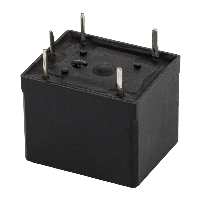 HLS8-T73 5-Pin SPDT Mini Power RelayCompact PCB-pin relay with 7 A or 10 A contacts, useful for checking coil drive and real load conditions.View Product →
Coil Stress, Control Voltage, and Driver Circuit Problems
The coil is the relay's control input, and it is often treated as an ideal load. It is not. A coil has resistance, inductance, and a pull-in current that changes with temperature. If the control voltage is too low, the armature may not seal firmly. The contacts may still close, but the magnetic gap remains larger than designed, so the coil draws more current and runs hotter. Over time, the insulation can weaken, the driver transistor can overheat, and the relay may chatter under vibration. A relay that "goes bad" in this condition may actually be reporting a power-supply or driver problem.
High control voltage is equally unhealthy. A 12 V coil driven by an unregulated 14.5 V supply may be acceptable if the relay is designed for that range, but a 24 V coil driven at 28 V continuously will dissipate more power and sit at a higher temperature. In industrial panels, long control cables can also introduce voltage drop during pickup and voltage spikes during release. Without a flyback diode or an RC snubber, the collapsing coil field can stress the driver and generate noise in nearby signal lines.
Low-current signal relays deserve the same respect. A telecom relay used for signal switching may have a 2 A or 3 A contact rating, but it is still an electromechanical part with a specified coil voltage and operate time. The HLS623F, for example, is a 6-pin SPDT mini telecom relay with PCB pins and a 2 A contact rating. It can be a good fit for communications equipment and low-power signal paths, but it should not be pushed into power-load switching simply because the package is small and available.
 HLS623F 6-Pin SPDT Mini Telecom RelayCompact 2 A PCB relay suited to telecom and low-power signal switching rather than power loads.View Product →
Moisture, Corrosion, and Contamination: Slow Failures That Look Sudden
Environmental attack is a quiet cause of relay failure. Moisture can enter through seams, terminal gaps, or damaged potting. Once inside, it may condense on cold contacts and create a high-resistance film. Dust and lint can block armature movement. Sulfur gases in industrial or automotive environments can corrode silver contacts. Cleaning fluids and conformal coating vapors can leave insulating films on contact faces. The relay may pass a bench test when dry and fail in the field after a temperature drop.
Corrosion often shows up first at the terminals, not inside the relay. A green or dark terminal block, a loose spade connector, or a cracked solder joint can mimic a relay failure. Before replacing the relay, inspect the socket and PCB side. In automotive applications, vibration plus humidity can wear through thin plating. In appliance controls, steam and detergent vapor can attack unsealed relays. In outdoor control cabinets, condensation cycles can be more damaging than direct rain because the moisture enters as vapor and condenses inside the housing.
Buyers should ask whether the relay is open, dust-covered, flux-tight, or washable, and whether the application requires conformal coating after assembly. A sealed relay is not automatically better for every design, because trapped internal pressure and process compatibility also matter. The safer approach is to define the environment clearly, then test the selected relay under humidity cycling, thermal shock, and any cleaning process used on the assembly line.
Heat, Ambient Temperature, and Poor Heat Management
Relay ratings are usually published at a reference ambient temperature, often 23°C or 25°C. A relay that carries 10 A in an open lab may not carry 10 A inside a sealed control box at 60°C. Contact resistance produces heat, and the coil produces heat whenever it is energized. If the relay is packed next to transformers, power resistors, or other relays, the local temperature can be much higher than the cabinet's average temperature. Plastic softens, spring tension changes, and coil insulation ages faster.
Continuous coil energization is another common blind spot. A relay designed for intermittent duty may not be intended to stay on for thousands of hours. Even when the coil is within its rated voltage, the temperature rise may push the contact and coil materials beyond their comfortable range. In compact appliance boards, the relay may be the tallest component and may sit in still air. In industrial panels, the relay may be mounted vertically on a DIN rail with poor chimney effect. Both layouts can shorten life.
The practical check is to measure the relay case temperature under the worst real operating condition, not on the bench. If the case is too hot to touch, the internal parts are hotter. Derating the contact current, increasing spacing, adding ventilation, or choosing a relay with a higher temperature rating may be more effective than simply replacing the failed unit with the same model.
Vibration, Mechanical Shock, and Poor Mounting
Relays are mechanical devices, and mechanical devices can be damaged by movement even when the electrical load is modest. In vehicles, vibration can fatigue spring members, loosen spade terminals, and crack solder joints on PCB-mounted relays. In industrial equipment, shock from nearby contactors or motors can cause the armature to chatter. A relay that is mechanically stressed may show no problem on a static test bench but fail when the machine starts or the vehicle drives over a rough road.
Mounting method matters as much as relay construction. A PCB relay should have proper pad support and not rely on the pins to hold the housing against vibration. A socket-mounted relay should use a retaining clip or a socket designed for the expected shock. Quick-connect terminals should be fully seated and not side-loaded by the wiring harness. In automotive relays, such as the 5-pin 30 A HLSCMA6 with PCB or quick-pin options, the installer should confirm that the harness strain is relieved and that the relay is not hanging on its terminals.
 HLSCMA6 5-Pin 30 A Automotive RelayPCB or quick-pin automotive relay for mounting layouts where harness strain and terminal support need checking.View Product →
When a relay fails in a high-vibration application, look for cracked solder, shiny wear marks on the armature, loose rivets, or terminal fretting. These are mechanical signatures, not contact overload signatures. Replacing the relay without fixing the mounting or harness strain usually leads to repeat failure.
Manufacturing Defects and Supplier Quality: What Buyers Should Check
Not every relay failure comes from the application. Manufacturing variation can create early failures through weak contact welds, contaminated contact surfaces, incorrect spring tension, incomplete sealing, or inconsistent coil winding. These problems are often invisible in a short functional test. They appear as a small number of returns, a batch with shorter life, or a field failure that cannot be repeated on the bench. For B2B buyers, the supplier's process control and material traceability matter as much as the relay's headline ratings.
A relay manufacturer should be able to explain how contact material is controlled, how coil resistance is checked, how sealing is verified, and how final inspection is sampled. Quality system certification is a baseline, not a complete answer. Helishun operates an ISO 9001 quality system and lists UL, TUV, CE, CQC, and RoHS compliance across its relay families. These documents help buyers clear market access and incoming inspection, but the purchase order should also define the exact model, coil voltage, contact form, load rating, and any application-specific test requirement.
Incoming inspection should not stop at "the relay clicks." A useful sample plan may include coil resistance, pickup and dropout voltage, contact resistance, insulation resistance, dielectric strength, and a load test at the specified current. For automotive or appliance programs, the buyer may also request temperature rise, humidity cycling, vibration, and electrical life data. If the supplier cannot provide a test report for the exact model and load condition, the buyer is taking on unmeasured risk.
How to Diagnose a Bad Relay Without Guessing
Diagnosis should follow the energy path from control signal to load. First confirm the coil is receiving the specified voltage and that the driver can supply the required current. Then check whether the coil resistance is within tolerance and whether the coil is open or shorted. Next inspect the contacts under load, not only with a continuity buzzer. A contact that shows continuity with no current may still fail when it must carry 10 A. Finally check the socket, PCB pads, terminals, and harness before condemning the relay.
Field return data usually clusters around a small number of repeat causes. The chart below uses a typical service pattern to show where inspection time is often best spent. It is not a universal laboratory distribution, so use it as a starting point for your own failure log.
Typical Field Failure Pattern by Cause
The chart points to a practical order of inspection: load, coil, environment, then mechanics. In many returned relays, the contact surface shows arc damage before the coil fails, which is why a simple coil test can wrongly clear a relay that is not safe under load. A relay supplier can help by sharing model-specific load curves, inrush guidance, and recommended suppression methods. For a design team, the fastest improvement is often to record the failed load, ambient temperature, switching frequency, and relay model together, then compare that record with the datasheet assumptions.
A basic test sequence should include visual inspection, coil resistance, pickup and dropout voltage, contact resistance, and a loaded switching test. If the relay is socket-mounted, test the socket separately. If the relay is PCB-mounted, inspect the solder joints and look for heat damage around the pins. Replace the relay only after the control voltage and load have been checked, because a new relay will fail the same way if the root cause remains.
- Confirm the actual coil voltage at the relay terminals while the circuit is energized.
- Measure coil resistance and compare it with the model datasheet at the same temperature.
- Check contact resistance and perform a loaded switching test with the real load type.
- Inspect terminals, sockets, PCB pads, and harness strain for heat or movement.
- Record ambient temperature, switching frequency, and any arc suppression used.
When to Repair, Replace, or Redesign
Replacing a failed relay is appropriate when the root cause is a one-time event, such as a loose terminal, a damaged socket, or a single contaminated batch. Replacing the same model without changing the circuit is risky when the failure repeats. If the contact shows welded faces, the load is probably beyond the relay's switching capability. If the coil is open, check the driver and suppression first. If the case is deformed, review heat and enclosure layout. If the failure rate is low but the field symptom is intermittent, inspect the socket and wiring before assuming the relay is at fault.
Redesign is often the cheaper path when the application has changed. A product that once used a resistive heater may now use a motor with higher inrush. A control panel that once ran at room temperature may now sit in a sealed enclosure outdoors. A 5 A relay may have been adequate for a signal load but is now switching a solenoid. In these cases, the correct fix may be a higher contact rating, a different contact material, a sealed housing, a socket with better retention, or an external suppression network.
For OEM and ODM programs, the redesign conversation should include the relay manufacturer early. A supplier that understands the load, duty cycle, and certification target can recommend a model that fits the existing footprint or propose a compatible alternative. This is especially useful when a legacy relay is being replaced and the mechanical layout cannot change.
Selection and Sourcing Checklist for B2B Buyers
A good relay purchase specification prevents many field failures before they happen. The buyer should define the load type, steady current, inrush current, switching frequency, coil voltage, ambient temperature, mounting method, and required certifications. The specification should also state the expected electrical life and the test method used to verify it. A relay manufacturer can then recommend a model based on data rather than guesswork. A wholesaler or distributor can help with availability, but the technical fit still belongs with the design and quality teams.
For automotive applications, check the pin count, contact rating, housing style, and vibration requirement. For appliance and instrument boards, check the PCB footprint, height, sealing, and heat tolerance. For telecom and signal switching, check contact rating, coil power, and signal-level reliability. For industrial control, check socket compatibility, DIN rail mounting, and suppression. The same physical package can contain very different contact materials and spring designs, so model-level confirmation is essential.
When comparing suppliers, ask for the exact model datasheet, certification scope, and a sample test report. Confirm whether the supplier is the actual manufacturer or a trading company, and whether OEM or ODM changes are supported. A reliable supplier should be able to explain derating, failure modes, and replacement compatibility without hiding behind a generic catalogue. Helishun has been manufacturing relays since 2000, operates an 8,800 square meter facility in Ningbo, and supports OEM and ODM cooperation across automotive, power, telecom, and socket product lines.
Need a relay supplier with documented materials? Review the Helishun company profile or contact the relay team with your load, coil voltage, and annual volume.
Frequently Asked Questions About Relay Failure
What causes a relay to go bad most often?
Contact overload and load mismatch are the most common practical causes. The relay may be rated for a steady current that looks sufficient, but the real load may have a much higher inrush or a destructive turn-off transient. Coil stress, moisture, heat, and vibration are also common, especially when the relay is installed in a sealed enclosure or a high-vibration environment.
Can a relay fail even if it still clicks?
Yes. A relay can click and still have welded, pitted, or high-resistance contacts. The coil may pull in normally while the contacts fail under load. This is why a continuity test without current is not enough. The relay should be tested with the real load or at least with a load that represents the application's current and inrush.
Why does a relay fail after a few months instead of immediately?
Many failure mechanisms are cumulative. Contact arcs remove material slowly, heat ages coil insulation, and moisture corrodes terminals over time. A relay that is marginally within rating may work for months before the damage reaches a tipping point. Repeat failures at the same interval usually point to a systematic load or environmental issue, not random defects.
Does a flyback diode prevent relay failure?
A flyback diode protects the driver from the coil's collapsing voltage, but it does not protect the contacts from load arcing. It can also increase release time, so the circuit design must account for that. Contact protection for inductive loads is a separate issue and may require an RC snubber, varistor, or other suppression method depending on the load.
Can low coil voltage damage a relay?
Yes. If the coil does not receive enough voltage to pull in firmly, the armature may chatter or sit in a partial stroke. The coil can draw more current and run hotter, and the contacts may not close with the intended force. The result can be erratic operation, welded contacts, or a burned coil. Always check the voltage at the relay terminals under load.
How do I know if the relay or the socket is bad?
Test the relay outside the socket and test the socket with a known-good relay. Inspect the socket for loose terminals, heat marks, corrosion, and cracked plastic. In many field failures, the relay is replaced but the socket remains the real problem. If the new relay works for a short time and then fails again, the socket and wiring should be the next focus.
Should I use a sealed relay in a humid environment?
A sealed relay can help, but the whole assembly must be considered. Trapped moisture, cleaning fluids, and conformal coating vapors can still create problems if the process is not controlled. The better approach is to define the humidity, temperature cycling, and cleaning process, then validate the selected relay under those conditions. In some cases, a sealed relay plus proper housing drainage or breathable membrane is more effective than sealing the relay alone.
What should a buyer ask a relay manufacturer before ordering?
Ask for the exact model datasheet, contact rating at the real load type, coil voltage range, temperature derating, electrical life, certification scope, and sample test report. Confirm whether the supplier is the manufacturer and whether OEM or ODM changes are supported. Also ask how the supplier handles traceability and failure analysis when a return occurs.
Final Takeaway: Find the Failure Signature Before You Replace the Relay
A relay rarely goes bad for a mysterious reason. It usually leaves a signature: blackened contacts from arcing, an open coil from heat or overvoltage, corroded terminals from moisture, cracked solder from vibration, or a deformed case from ambient heat. Once that signature is read correctly, the fix becomes clearer. Replacing the relay may restore the machine for a day, but if the load, coil circuit, environment, or mounting remains unchanged, the new relay is likely to fail in the same way.
For maintenance teams, the fastest path is to record the relay model, coil voltage, load type, switching frequency, ambient temperature, and hours to failure. For design teams, the fastest path is to compare that record with the datasheet assumptions and adjust the selection. For buyers, the fastest path is to work with a relay manufacturer that can provide model-level data, consistent quality, and practical support for OEM and ODM programs.


