

 English
 中文简体
中文简体Content
The key to connecting a 7-pin automotive relay is identifying the functional definitions of its pins. These typically include power input (pin 30), ground (pin 85), switching signal (pin 86), normally open contact (pin 87), normally closed contact (pin 87a), and two additional sensing or feedback pins (common in trailer control or flasher applications). During operation, connect the main power line to terminal 30, the signal control line to pin 86, the loop ground to pin 85, and the load device to pins 87 or 87a according to the logic. Finally, connect the remaining dedicated sensing pins according to the specific circuit diagram to ensure the integrity of the vehicle's circuit control logic.
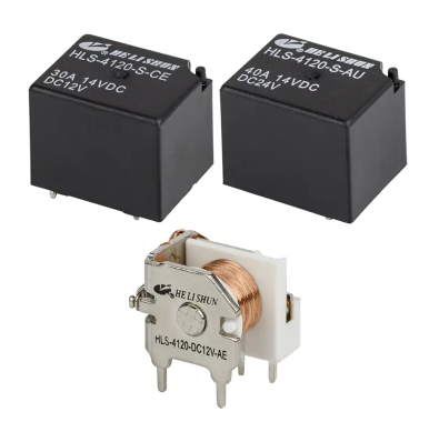
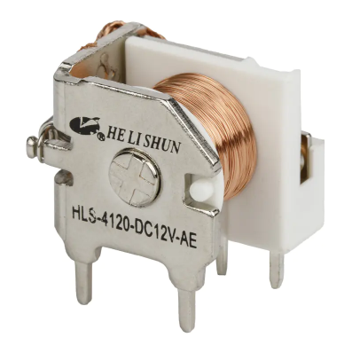
Understanding the Structure of a 7-Pin Automotive Relay
Compared to common 4-pin or 5-pin relays, 7-pin automotive relays are typically used in more complex systems, such as European trailer receptacle control, high-power lighting switching, or complex electronic control unit (ECU) feedback systems.
Multifunctional integration: It can achieve current distribution and signal feedback within a single unit.
Standardized interface: Despite having more pins, its core still follows the electromagnetic induction principle of standard automotive relays.
Detailed Wiring Guide for 7-Pin Automotive Relays
1. Pin Definition Identification
Before starting wiring, always refer to the circuit diagram on the 7-pin automotive relay housing. Common pin configurations are as follows:
- 30 Pin: Constant power supply (from the battery, fuse required).
- 85 & 86 Pins: Coil control terminals (connect to control switches).
- 87 & 87a Pins: Output terminals (control load switching).
- Two additional pins (e.g., C, R, or S): Typically used for load detection or signal synchronization (e.g., trailer turn signal status monitoring).
2. Preparing Connection Tools
Use high-specification automotive-grade wire and crimp terminals. Since relays typically carry high currents, poor contact can cause overheating and even melt the plastic base.
3. Grounding and Safety Protection
Ensure that the 85 pin is connected to a reliable chassis ground. For precision systems controlled by 7-pin automotive relays, it is recommended to install a current-matching fuse on line 30 to protect the entire vehicle electrical system.
Common Application Scenarios Analysis
Professional Advice for Improving Circuit Reliability
To ensure the long-term stable operation of 7-pin automotive relays, please pay attention to the following technical details:
Select the Appropriate Current Specification: Different relay models have different load capacities. If driving a high-power fan or heater, ensure the relay's rated current (e.g., 30A or 40A) is greater than 1.25 times the load current.
Prevent Back EMF: When connecting control circuits (85/86), if the system does not have integrated diodes, it is recommended to install them yourself. This effectively prevents the surge current generated when the coil loses power from damaging the vehicle's electronic control modules.
Environmental Protection: Relays should be installed away from high temperatures and direct water splashes. Using a relay base with a sealing ring can significantly extend contact life and prevent excessive voltage drop due to oxidation.
7-pin models often have specific logic; before wiring, please confirm whether it is a "normally open" or "combination function" type to avoid short circuits.


