

 English
 中文简体
中文简体Content
In modern electronic equipment manufacturing, PCB power relays are core components for achieving automated control and circuit protection. Whether in industrial control systems, home appliances, or new energy vehicle charging stations, the performance of the PCB power relay directly determines the stability and safety of the entire device.
If a relay malfunctions, it may lead to short circuits, load failure to start, or abnormal system shutdown. Therefore, mastering how to test PCB power relays is an essential skill for electronic engineers and maintenance personnel.
1. Static Testing: Physical Appearance and Contact Resistance Inspection
Before power-on testing, a preliminary static inspection should be performed to rule out obvious hardware damage.
Visual Inspection: Observe the relay casing for cracks, burning, bulging, or pin oxidation.
Coil Resistance Test: Use the resistance range (ohms) of a multimeter to measure the resistance between the relay coil leads.
Normal: The resistance value should conform to the nominal value in the datasheet.
Abnormal: If the resistance is infinite, the coil is open-circuited; if the resistance is close to zero, the coil is short-circuited.
Normally Closed/Normal Open Contact Test:
In the unenergized state, the normally closed (NC) contact should conduct (extremely low resistance).
The normally open (NO) contact should open (infinite resistance).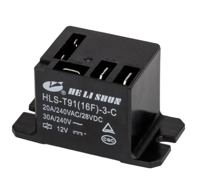
2. Dynamic Test: Pull-in and Release Voltage Detection
The dynamic test aims to verify the switching capability of the PCB power relays under actual operating voltage.
Pull-in Voltage Test: Slowly adjust the DC adjustable regulated power supply to increase the voltage applied to the coil until a clear "click" is heard. Record the voltage at this point; it should typically be less than 75% of the rated voltage.
Release Voltage Test: After the relay pulls in, gradually decrease the voltage. Record the voltage when the contacts reset. The release voltage should typically not be lower than 10% of the rated voltage.
Expert Tip: If the pull-in voltage is too high, it indicates potential wear in the relay's internal mechanical structure or aging of the electromagnetic coil, which can lead to unstable operation in environments with large voltage fluctuations.
3. Load Performance and Contact Voltage Drop Test
For PCB power relays, the ability to carry high current is crucial.
Contact Resistance: With the relay in the energized state, measure the resistance between the contacts using a milliohm meter. Over time, relay contacts may develop an oxide layer or carbon buildup, leading to increased contact resistance, which can cause overheating or even soldering.
Load Test: Observe the contact temperature rise after operating at rated current for a period of time.
4. Insulation Resistance and Withstand Voltage Test
Insulation testing is essential to ensure the safety of both the high-voltage and low-voltage sides.
Coil-Contact Insulation: Measured using an insulation resistance meter (megohmmeter). Typically, an insulation resistance greater than 100MΩ is required at 500V DC.
Dielectric Strength: Verifies whether the relay will break down under instantaneous high voltage.
Regular scientific testing of PCB power relays not only effectively extends equipment lifespan but also prevents potential safety accidents. Through the comprehensive testing described above, from static to dynamic, from physical properties to load capacity, you can accurately determine the health status of the relay.
When purchasing or replacing power relays, it is recommended to prioritize high-quality PCB power relay brands that meet international standards (such as UL, VDE, CQC) to ensure the long-term reliability of the circuit board under complex operating conditions.


